Navigation
Scale and motor encoder inputs (15W HDD socket)
The SPA3-2 can support up to 4-axis scale inputs and 3-axis of motor encoder inputs. Each input supports a RS-422 (TIA/EIA-422) standard quadrature interface with an edge rate of up to 30 MHz, also supported are discrete and tristate error signals as well as readhead limit switches.
The scale inputs support absolute readheads using the BiSS protocol as used by Renishaw Resolute™, 18, 26, 32 and 36 bit protocols are supported.

Pin number | Incremental readhead | Motor encoder | Absolute encoder |
|---|---|---|---|
1 | Not connected | Not connected | Reserved |
2 | 0 V supply | 0 V supply | 0 V supply |
3 | - Error | Not connected | Reserved |
4 | - Reference mark | Not connected | Reserved |
5 | - B signal | - B signal | MA- |
6 | - A signal | - A signal | SLO- |
7 | + 5.25 V supply | + 5.25 V supply | + 5.25 V supply |
8 | + 5.25 V supply | + 5.25 V supply | + 5.25 V supply |
9 | 0 V supply | 0 V supply | 0 V supply |
10 | Limit switch Q | Not connected | Reserved |
11 | + Error / limit switch P | Not connected | Reserved |
12 | + Reference mark | Not connected | Reserved |
13 | + B signal | + B signal | MA+ |
14 | + A signal | + A signal | SLO+ |
15 | Inner screen | Inner screen | Inner screen |
Shell | Outer screen | Outer screen | Outer screen |
NOTE: To cater for readhead cable voltage drops the supply voltage can be adjusted, this is done via the UCCassist-2 software. The voltage can be set to 5.25 V (default), 5.75 V, 6.25 V and 6.75 V.
The voltage selected applies to all readheads and motor encoders.
NOTE: Only three scale inputs are available whilst motor encoder feedback is used.
Scale signal interface circuit
SPA3-2 input circuits for CMM readhead and motor encoders.

NOTE: Reference input is not available on motor encoder inputs.
Absolute output interface circuit
Scale output signal circuit (BiSS protocol readheads only).

Readhead error interface circuit
Supports Renishaw encoder error signals (e.g. for the RGH24). If an error signal is not present on the connected readhead the -error input (pin 3) must be linked to +5 V (pin 7).

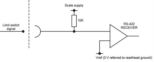
Limit switch interface circuit
Supports Renishaw encoder scale-based limit switch signals (e.g. for the RGH24).
