Safety first - the position determination and checking algorithms of the RESOLUTE™ true-absolute optical encoder
This white paper gives an overview of the operation of the RESOLUTE absolute encoder and describes in detail the safety aspects of its position determination and checking algorithms.
Introduction
The RESOLUTErange of true absolute encoders operates in a fundamentally different way from traditional absolute encoders, allowing them to output an error flag that is certain to be set if the position output is incorrect. This provides increased levels of safety for end users of motion systems while simplifying the design process for the system builder.
RESOLUTE calculates position on demand, whereas traditional absolute encoders operate on a continuous basis. In use, the readhead receives a series of request signals from the host control system. Each time it receives a request, the readhead determines position by two independent methods (described below) that work by completely different principles, avoiding the risk of a common cause failure. The resulting positions are compared to decide whether to set the error flag that is appended to the position sent to the control system. This means that the control system can rely on the error flag sent out by the readhead. If the error flag is not set then the position output is certain to be correct.
Method of position calculation
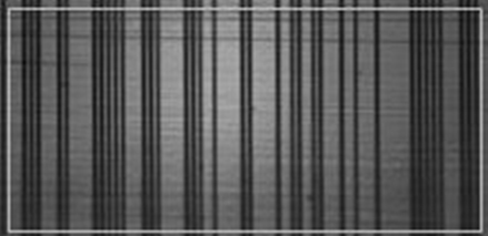
RESOLUTE is an optical encoder that uses a measuring scale consisting of dark lines on a bright substrate as shown in Figure 1. The fundamental scale period is 30 µm but selected lines are missed out in order to encode absolute position information.

Figure 1: Image of absolute scale

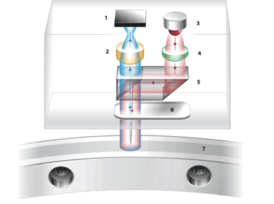
Figure 2: RESOLUTE optical scheme
1. Image sensor 2. Detector lens 3. LED 4. Collimating lens
5. Beam-splitting prism 6. Readhead window 7. Absolute scale
When the encoder receives a position request, it captures an accurately timed snapshot image of a region of the scale. A light emitting diode (LED) and an electronic shutter on the image sensor, as shown in Figure 2, are driven for around 100 ns. This results in an image that is timed to within ±20 ns and is free from motion blur. The image is then transferred to a digital signal processor (DSP) located within the readhead and position is calculated using two separate algorithms:
Algorithm 1 calculates position by decoding a single image without using any information about previous positions. The first stage of the process is to calculate the phase of the image; this stage is similar to that performed by incremental encoders and results in an answer that is some fraction of the fundamental scale period, i.e. a value between 0 and 30 µm, with a resolution of better than 1 nm. Each image of the scale extends approximately 2 mm in the direction of measurement and the scale is designed such that in any one image there are sufficient dark lines to calculate phase accurately. This phase calculation defines the short distance accuracy, resolution and noise performance of the encoder.
The phase information is used to locate the centre of each potential line on the scale. A correlation is then performed on the image at each of these locations to ascertain whether there is a dark line present or not. This results in a 65-bit binary number corresponding to the scale pattern directly below the readhead. Only a quarter of these bits are required to define a unique position. The remaining bits provide redundant information so that the correct position can be ascertained even if some of the scale is obscured. An error detection and correction algorithm is then used to convert the bit sequence to the readhead's coarse absolute position. The full algorithm 1 position is formed by combining the coarse position (whole number of scale periods) with the phase information.
Algorithm 2 calculates position by linear extrapolation from the two most recent previous position readings. To do this, it assumes that the velocity of the encoder since the previous reading is the same as that measured between the two previous positions. The error in this calculation is determined by the time between sequential readings, the accuracy of the previous readings, any timing uncertainties and the relative acceleration of the readhead and scale. For a typical system that requests position every 62.5 µs with a maximum acceleration between the readhead and scale of 100 m/s2 (10 g), algorithm 2 will have a maximum error of ±1.2 µm. The readhead makes sure that there is never more than 75 µs between images by capturing extra images between requests if necessary.
Position comparison
Once the two positions have been calculated, the encoder makes a decision about what position to output and whether to set the error flag. The phase part of the algorithm 1 calculation is very robust. If contamination is introduced to the scale then the phase information will become noisier and can be distorted. However, even in extreme circumstances, the position error caused by this will be less than one micrometre. The phase information will still be reliable in the presence of significant contamination but the error correcting capability of the coarse position calculation may be insufficient to decode the absolute position correctly.
The position calculated by algorithm 2 provides a robust coarse position as only extreme acceleration (>2000 m/s2) can cause an error big enough to change the coarse position. However, the fine position (phase) from algorithm 2 is not very accurate owing to the assumption that the velocity is constant.
During operation, if the coarse positions calculated from the two algorithms agree, which is equivalent to the full positions being within ±15 µm (half a scale period) of one another, then the readhead outputs this coarse position along with the phase from algorithm 1. At the same time an internal counter is set to zero; the significance of this counter will become apparent in due course. If the coarse positions disagree then the readhead outputs the phase from algorithm 1 along with the coarse position from algorithm 2, and also increments the internal counter. If the value of the internal counter ever exceeds four, then the readhead sets the error flag as it is no longer certain that the position output is correct. It is useful at this point to examine a few examples of causes for setting the error flag.
Example 1
Assume that the readhead passes over a region of contamination that exceeds the error correcting capacity of the scale code. The result will be an incorrect coarse position from algorithm 1. However, it will have correct phase, albeit with sub-micrometre inaccuracy caused by the presence of the contamination. The readhead will record the discrepancy between the coarse positions internally (by incrementing its counter) and will output the correct coarse position from algorithm 2 along with the correct phase from algorithm 1. If the readhead fails to ascertain the correct coarse position from algorithm 1 for five consecutive images then it will set the error flag to indicate that it is no longer sure of position. If algorithm 1 correctly ascertains the coarse position after four or fewer images then the counter is reset and the position output continues as before.
Example 2
Assume that the readhead is operating normally and then experiences an acceleration of ~10 000 m/s2, equivalent to decelerating from 2 m/s to stationary over 100 µm, which could be caused by running a machine into a rigid end-stop. In this scenario the position from algorithm 1 will always be correct whereas the position from algorithm 2 will lag the correct position by no more than a few scale periods. The readhead will assume (incorrectly) that the coarse position from algorithm 2 is correct and will output this along with the correct phase from algorithm 1. From this point on the coarse positions from both algorithms will always disagree. The readhead will calculate five positions that slightly lag the actual position before setting the error flag.
Example 3
For this example, assume that both algorithms fail at the same time. Take the unlikely situation where ionising radiation corrupts a region of the memory within the readhead's processor such that the positions from both algorithms are corrupted. Because the algorithms are so different in the way they calculate position, it is inconceivable that they will be corrupted such that they both produce the same wrong answer. The readhead will therefore identify that the coarse positions differ and will increment its counter and output the incorrect position made up from the coarse part of algorithm 2 and the phase of algorithm 1. Since algorithm 2 is based on previous readings, from this point on its answer will always be incorrect. Therefore even if algorithm 1 recovers to give the correct answer the readhead will still raise the error flag after calculating five incorrect positions.
Error flag response
In these examples, it has been shown that the readhead can output up to five incorrect positions before setting the error flag. For a system requesting position every 62.5 µs, the time between outputting the first incorrect position and raising the error is 313 µs. For a slower system requesting position at 500 µs intervals then this time will be 500 µs, as the readhead will have processed six further images between each pair of requests in order to make sure that the time between images never exceeds 75 µs. In both of these cases, the time between outputting incorrect position and raising the error flag is sufficiently short that appropriate action can be taken in response to the error flag before the incorrect data can influence the control system.
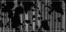
Figures 3 and 4 show examples of scale contamination that still allow phase to be determined but typically defeat absolute code extraction. In such cases the mechanisms described will either succeed in preserving position or warn to the contrary by setting the error flag.

Figure 3: Particle contamination obscures large regions of the scale but phase information can still be determined.

Figure 4: Grease contamination cause complex scattering of light but phase information is only minimally disturbed.
System power-up
An assumption has been made up to this point that there is always enough historical data for algorithm 2 to extrapolate position. This is not the situation straight after power is of the readhead, as there can be no extrapolated position to compare to that read from the scale. In this situation, two methods are used to give increased confidence in the position of the readhead relative to the scale.
First, the readhead automatically sets the error flag if the image contrast is unacceptable. Second, a restriction is placed on the allowable extent of error correction. Since the scale code uses redundant data to ensure a large number of bits differ between valid sequences, this restriction on correctable bits substantially limits the risk that one bit sequence can be incorrectly decoded as a false position. These two restrictions mean that the readhead's contamination immunity is slightly reduced during power-up. However, this is countered by the readhead taking a large number of images during its start-up procedure so that noise will not restrict its ability to ascertain position.
Furthermore, the scale code is designed such that in the very unlikely event that the readhead does ascertain an incorrect position at power-up, the discrepancy will be detected within a movement of 500 µm. At this point, the error flag will be set.
CRC
Once the position and error signals have been calculated by the readhead, a cyclic redundancy check (CRC) is calculated and appended to the data before it is transmitted to the host controller. Transmission occurs via differential signalling along a double-shielded cable. On receipt of the data, the CRC can be recalculated and compared with the transmitted value. A difference in these values indicates that the data has been corrupted during transmission. This ensures that any corruption of the position or error signals is detected. A further advantage of using serial protocols over traditional quadrature systems is that each transmission is independent, so errors in transmission cannot accumulate. This, along with the unique operation of RESOLUTE, provides users with a crucial safety advantage because miscounting, position drift or count ‘runaway' cannot occur.
Conclusions
Aside from providing excellent metrology in normal service, the design of RESOLUTE is specifically optimised to assure dependable position output despite fault conditions or abnormal operation. System designers can trust RESOLUTE to report true position or flag the contrary. Users are protected from uncontrolled movements and crash risks, with benefits to yield and throughput and, most importantly, safety.
