Navigation
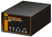
OPI 6 legacy interface
The OPI 6 automatically identifies and provides power to the OTP6M probe
 The interface allows rapid integration onto a CMM
- It includes all the necessary electronics to condition the output signals from both standard touch-trigger probes and the OTP6M probe
- If another multiwired probe is fitted the OIP 6 will route signals to an appropriate Renishaw interface
- The OPI 6 have the capability of PICS (Renishaw's product interconnection system) or SSR outputs and allows the user to remotely select the 1D or 3D modes of operation
Front panel

1 POWER LED
ON when power is supplied to the interface.
2 LASER LED
ON when power is supplied to the OTP6M probe.
3 PROBE TYPE LED
ON when OTP6M probe fitted.
4 PROBE TYPE LED
ON when standard touch-trigger probe fitted.
5 PROBE SEATED LED
ON when no optical trigger point (or stylus deflection).
OFF when an optical trigger point is taken (or stylus deflected).
6 PROBE DAMPED LED
ON when PROBE DAMPing is selected using PICS.
Rear panel

7 FCC label (on side panel)
This label indicates conformance to FCC regulations (USA).
8 Configuration switches:
Switch no. | Position | Designation |
|---|---|---|
1 | UP | SYNC high for probe seated, low for probe triggered. SSR open for probe seated, closed for probe triggered. |
DOWN | Output polarity reversed. | |
2 | UP | OPI 6 connected to standard touch-trigger probes via PICS socket. |
DOWN | OPI 6 connected to standard and multiwired probes via the probe cable. | |
3 | UP | Normal PICS STOP position. |
DOWN | OPI 6 will not assert trigger in response to an external PICS STOP signal. | |
4 | UP | Multiwire bypass active. |
DOWN | Multiwire bypass inactive. |
9 Interface serial number
This unique number allocated to each OPI 6 should be quoted when contacting Renishaw for help or service.
10 PICS in: 9-pin D-type socket

Pin no. | Designation |
|---|---|
1 | PICS STOP (bi-directional) |
2 | Probe power off (bi-directional) |
3 | 0 V |
4 | LED drive (anode) |
5 | Probe signal |
6 | PICS pull-up |
7 | Probe DAMPing (output from CMM) |
8 | LED off |
9 | Probe signal |
Body | Cable screen |
11 PICS out: 9-pin D-type plug

Pin no. | Designation |
|---|---|
1 | STOP |
2 | Probe power off |
3 | 0 V |
4 | - |
5 | SYNC |
6 | HALT |
7 | Probe Damping |
8 | LED of |
9 | - |
12 CMM input / output: 7-pin DIN socket
CAUTION: This connector does not have the same functions on pins 1, 3, 6 and 7 as the PHC9 / PHC10 or any other Renishaw interface. Incorrect connection may affect system performance or cause damage to associated equipment.

Pin no. | Designation |
|---|---|
1 | 3D mode select * |
2 | Screen |
3 | Reserved for Renishaw use |
4 | SSR |
5 | SSR return |
6 | IN RANGE output ** |
7 | Error output *** |
* 3D mode is selected by connecting pin 1 to pin 2 (screen)
** When the probe is operating within its working range the IN RANGE output is 5 V (at all other times 0 V)
*** When an error occurs this output is 5 V (at all other times 0 V)
13 Version number label
This label indicates the modification level of the OPI 6. This label may be relevant when integration with other systems is under consideration and should always be quoted when contacting Renishaw for help or service.
14 Interface: 15-pin high-density 'D' type socket
Provides connection between the OPI 6 and one other Renishaw multiwire probe interface via a PL101 cable.
15 Probe head: 15-pin high-density 'D' type socket
This socket accepts the multiwired cable from the PH10M / PH6M probe heads.
16 Mains power IEC socket
The OPI 6 incorporates automatic voltage selection.

