Stran trenutno ni na voljo v vašem jeziku. Lahko si ogledate strojni prevod, ustvarjen s storitvijo Google Translate. Te storitve ne zagotavljamo mi in rezultatov prevoda nismo preverili.
Za dodatno pomoč se lahko obrnete na nas.
Laser interferometer error-proofs linear scale calibration
To achieve consistent sub-micron measurement accuracy, an automated line scale calibration system developed by the Standards and Calibration Laboratory (SCL) in Hong Kong made automatic error compensation a key design criteria. A Renishaw XL-80 laser interferometer and XC-80 compensator were used to successfully manage any sources of Abbe error, as well as changes in environmental conditions.
Background
Precision linear scales are often deployed in high-accuracy length measurement equipment, including comparators, microscopes and surveying instruments, where they provide an accurate benchmark for precisely measuring distances or travel.
Generally made of glass, linear scales are precisely engraved on their surface with equidistant parallel lines running perpendicular to the line scale axis. To measure and verify the distances between line scale graduations, high precision instruments are needed.
The Standards and Calibration Laboratory, a part of the Innovation and Technology Commission of Hong Kong's Special Administrative Region, is responsible for formulating and maintaining physical measurement reference standards for the Hong Kong region.
It provides local users of measurement standards and measurement instruments with calibration services, to ensure that they are able to accurately perform their measurement tasks and correctly trace their work back to the relevant standards.
SCL set itself the task of designing and manufacturing a new automated linear scale calibration system capable of achieving submicron measurement precision. Importantly, it would need to be able to compensate automatically for Abbe errors caused by the minutest of angular displacements in any of the equipment, and any variation in environmental conditions.

Challenge
Described by Ernst Abbe of Zeiss in 1890, the Abbe Principle has been called ‘the principle of alignment' and it states: “If errors of parallax are to be avoided, the measuring system must be placed co-axially (i.e. in line with) the line in which displacement (giving length) is to be measured on the workpiece.”
An Abbe error is therefore introduced when a point to be measured is separated laterally from the axis of measurement, and when the positioning system is subject to angular motion. It causes the measured displacement to appear shorter or longer than the true displacement. The spatial separation of measured point and axis of measurement is called the Abbe offset.
As a very simple illustration, consider a measuring caliper. Between the axis of the scale and the axis of measurement (formed between the jaws) there is an Abbe offset. Any issues of calliper straightness, squareness or ‘play' will all lead to an angular movement in the jaw and therefore an Abbe error.
J.B. Bryan who described the Abbe Principle as, “the first principle of machine design and dimensional metrology”, went on to restate it more in machine terms as: “The displacement measuring system should be in line with the functional point whose displacement is to be measured. If this is not possible, either the slideways that transfer the displacement must be free of angular motion or angular motion data must be used to calculate the consequences of the offset.”
In simple terms, the measurement of the accuracy of the graduations on a line scale are performed by measuring the distance between a reference line (generally the zero position) and the target graduation. Imaging analysis and compensation technology then have to be applied, so that the system can calculate and adjust the line scale reading positions, and thereby reduce the Abbe error.
However, when actually using such systems, it's also necessary to factor in real-world influences and other uncertainties in the design. For this reason, it is essential that effective compensation for errors caused by a variety of environmental and human factors is incorporated. In this case, SCL was actually located on the 35th floor of a 48-floor building, so even vibrations caused by wind and traffic needed to be taken into account.
Automation
In response to operator input the sliding stage moves to a default position for a target line measurement. Once stationary, the laser interferometer reads the positional data and the camera takes images of the graduated scale.
The images are then analysed to obtain the current position (using the distance from the zero position to the equivalent pixel value displayed). The position is compared with the actual calculated position, and the system then compensates for the difference by instructing the sliding stage to fine-tune the position.
Next, the interferometer takes another reading of the position data. The entire process is repeated a number of times until the error is within the specified pixel range and the final line position is obtained.

Precision stabilised laser source
The system design uses the Renishaw XL-80 laser interferometer to compensate for Abbe errors in the measurement system relating to any kind of angular displacement incurred in the setup. This could relate to sliding stage linearity, line scale placement or reflector positioning, for example.
With a nominal wavelength of 633 nm, the interferometer ensures a linear measurement accuracy of ±0.5 ppm thanks to a precision stabilised laser source and accurate environmental compensation. Readings can be taken at up to 50 kHz, with a maximum linear measurement speed of 4 m/s and a linear resolution of 1 nm, even at maximum speed. All measurement options are based on interferometric measurements, assuring greater confidence in the accuracy of the data recorded.
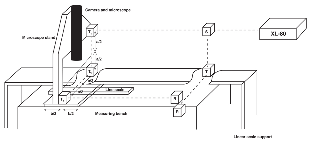
The interferometer setup employs a classic linear measurement configuration. The laser beam is split into two paths as it passes through beam splitter S, with one path forming a reference beam that passes through transfer lens T and reflector R back into the laser source probe, and the other beam passing through transfer lenses T1, T2 and T3 and reflector R to form a length change measurement beam.
In the SCL system, the XL-80 was used with the XC-80 compensator. Environmental conditions are measured using internal sensors for air pressure and humidity, with respective accuracies of 1 mbar and 6%, as well as three material temperature sensors and an air temperature sensor, having 0.1°C and 0.2°C accuracy respectively.
Solution
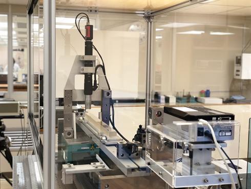
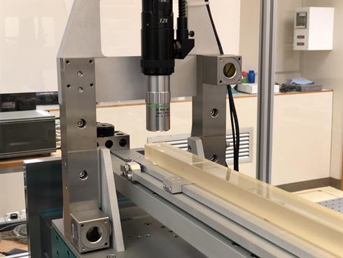
SCL's measuring system arrangement is shown in Figure 1. It uses a displacement method whereby the measuring device travels on a gantry above a fixed linear scale to measure the distance between a zero position and a linear scale graduation. The whole assembly is mounted on a vibration-damping table floated with air, and for better temperature profile control an enclosure is used.
The measurement is performed by a high-resolution microscope, mono CCD camera and a pixel-counting software algorithm, mounted on a sliding air bearing stage driven by an AC/DC mode piezoelectric motor. The system's sliding stage achieves a linearity of 0.9 µm for a measurement travel of 800 mm and repeatability of 20 nm. The maximum roll, pitch and yaw are each ± 0.5 arc seconds.
To compensate for any Abbe error, the SCL system then adopts an approach built on J.B. Bryan's thinking. Instead of using angular motion data to calculate a compensation value, it uses a symmetrical laser path on both sides of the axis of measurement. In this way any angular movement detected, that leads to either an increase or decrease in reading due to Abbe error, can be automatically compensated for.
Results
SCL has successfully developed a highly accurate automated line scale calibration system. Supporting line scales up to 750 mm in length, the system has a measurement uncertainty of just 0.15 nm - 0.41 nm.
In system testing a 500 mm glass scale calibrated by the Korean Institute of Standards and Science (KRISS) was used as an artefact to validate the calibration system. A total of 23 distances between scale graduations and the zero were selected as measurands.
Measurement results were compared with the values obtained from KRISS. The differences in measurement values were all within their individual measurement uncertainties and well within normalised error ratio of 0.7.
In the system, the root-sum-square of the Abbe error, caused by the 5 sec of arc in pitch and yaw of the microscope sliding stage for a distance of 100mm can be calculated to be 3.4 µm. In-depth analysis has shown that with the integration of the XL-80 interferometer, this Abbe error figure is reduced by 95%.


