Navigation
UCC T5 troubleshooting
UCC T5 visual diagnostics
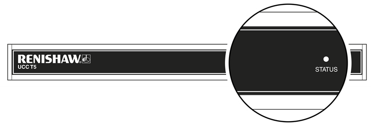
A visual indication of the system status is provided by a multicoloured LED on the front panel. The LED provides assistance in diagnosing system faults.

LED | Description | |
|---|---|---|
No LED | No power to unit. | |
Continuous blue | Unit has overheated. | |
Continuous red | Issue with comms link. Reboot unit and configure IP. | |
Continuous green | Normal operation. | |
Slow green flash | Unit waiting for download. | |
Slow blue flash | Contact your nearest Renishaw support office. | |
Slow red and blue flash | Check that the file being downloaded is appropriate for the controller. | |
Slow blue and green flash | An excess of 48 V is being supplied. Use correct power supply and reboot. | |
Slow green and red flashes | Scale issue, reboot unit. | |
Fast blue flash | Contact your nearest Renshaw support office. | |
Fast red flash | IP configuration mode. | |
Fast green flash | Comms lost to PC. Resync unit. | |
One grouped red flash | Contact you nearest Renishaw support office. | |
One grouped blue flash | Power supply has begun supplying excess power. Replace power supply and reboot. | |
Two grouped red flash | Reboot the unit. | |
Two grouped blue flash | An overcurrent has been detected on the head power supply. This might be caused by a suspect cable between the controller and the head. A reboot is required. | |
Three grouped red flashes | Contact you nearest Renishaw support office. |
Fatal faults
Situations can occur that make it inadvisable or dangerous to continue using the CMM servo system. These are known in this document and UCCassist-2 as fatal faults. A list of fatal faults are shown below and will be indicated through the user's software (for example UCCserver):
- A report of the emergency stop switch being active
- Air pressure is too low
- Crash switch operated, if fitted
- A scale reading failure
- An indicated overspeed (calculated from the rate of change of position)
- Outer limit switch active
NOTE: Other faults not classed as fatal can prevent the CMM's operation.
Motors will not engage / re-engage
Symptoms
Either the servo drives will not engage when the controller has been sent the ‘engage' command, or the drives have disengaged automatically and will not re-engage.
Possible causes (or reported causes)
After the unit is switched on and before the system is allowed to engage, it must be configured for motion (i.e. the machine, servo and move parameters must be sent to the controller).
Any of the 'fatal faults' will prevent the system from engaging. In addition, the following will disengage the servo motors;
- A reported failure from a servo power amplifier (amplifier feedback signal)
- The absence of the feedback signal from the motor contactor
- The following list can also inhibit drive engagement or re-engagement
- The probe being deflected
- Any outer limit switch being operated or a soft limit exceeded
Tests / cures
UCCassist-2 can be used for further help with this by displaying the system status, the status bytes and signals.
The amplifier and motor contactor feedback signals can also be examined using the ‘input signals' window in UCCassist-2.
NOTE: A scale error will cause the UCC T5 to enter an error state which is not recoverable within a metrology application environment. If a scale error occurs it will be necessary to reinitialise the installation due to the possibility of lost scale counts and metrology being affected.