Navigation
UCC T5 system connection
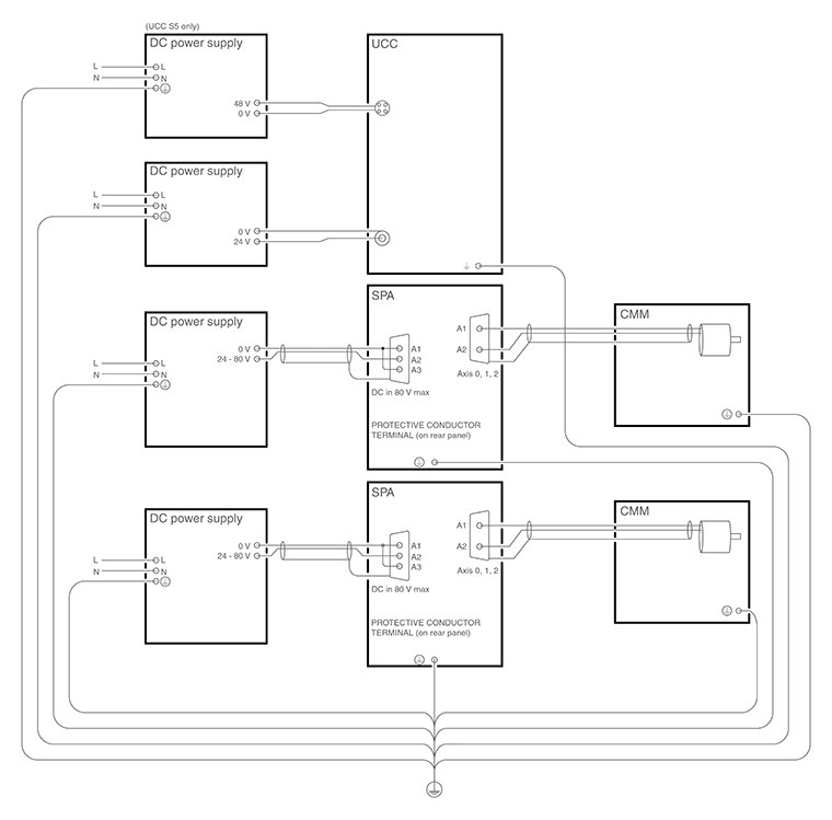
Earth bonding scheme
PH20 interconnection diagram
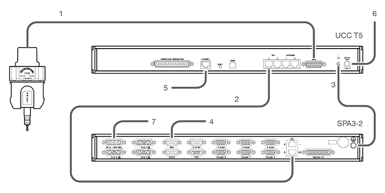
Key | Description |
|---|---|
1 | PH20 orange head cable |
2 | CAT 5E 300 mm cable (supplied) |
3 | 16 / 0.2 mm earth connection |
4 | MCU connection |
5 | CAT 5E ethernet cable (5 m cross-over cable supplied) to host PC |
6 | 24 V power supply (supplied) |
7 | 24 V - 80 V power supply (not supplied) |
Cable connections
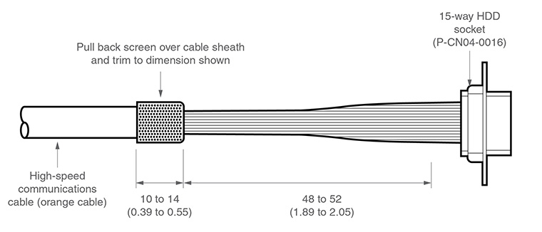
The cable connection to the head uses a standard 15-way high-density D connector. The cable should be connected and terminated as detailed below. It is mandatory that the Renishaw universal machine cable is used.
Various lengths of cable are available and include pre-crimped options for ease of installation.
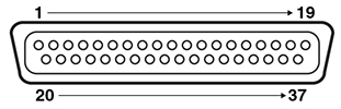
The following image shows the pin numbers for each connector end view of the Renishaw universal machine cable.
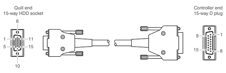
| 15-way HDD socket pin number (quill) | Function | Core colour | 15-way D plug pin number (controller) |
|---|---|---|---|
11 | Comms D+ | Green | 1 |
2 | 0 V | Black | 2 |
1 | Comms U+ | Orange | 3 |
7 | 0 V | White | 4 |
13 | Motor B0 | Blue | 5 |
3 | +20 V | Red | 6 |
4 | Motor A2 | Grey | 7 |
10 | Motor A0 | Pink | 8 |
9 | 0 V | Inner screen * | 9 |
12 | Comms D- | Green / black | 10 |
6 | Comms U- | Orange / black | 11 |
8 | +20 V | Clear | 12 |
14 | Motor B1 | Violet | 13 |
15 | Motor B2 | Yellow | 14 |
5 | Motor A1 | Brown | 15 |
Shell | Outer screen | Shell |
* NOTE: In pre-crimped cables this will be yellow / green.
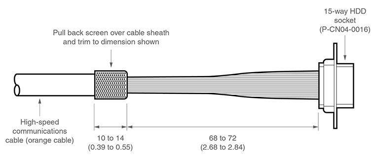
Ensure that the inner screen is not shorted to the outer screen at either end of the cable. A short can be prevented by using a small piece of heatshrink or other suitable method.
Preparation of Renishaw universal machine cable for quill mounted systems
Preparation of Renishaw universal machine cable for shank mounted systems
Temperature compensation connector
Pin number | Channel | Pin number | Channel |
|---|---|---|---|
1 | Channel 1 input | 20 | Channel 1 return |
2 | Channel 2 input | 21 | Channel 2 return |
3 | Channel 3 input | 22 | Channel 3 return |
4 | Channel 4 input | 23 | Channel 4 return |
5 | Channel 5 input | 24 | Channel 5 return |
6 | Channel 6 input | 25 | Channel 6 return |
7 | Channel 7 input | 26 | Channel 7 return |
8 | Channel 8 input | 27 | Channel 8 return |
9 | Channel 9 input | 28 | Channel 9 return |
10 | Channel 10 input | 29 | Channel 10 return |
11 | Channel 11 input | 30 | Channel 11 return |
12 | Channel 12 input | 31 | Channel 12 return |
13 | Channel 13 input | 32 | Channel 13 return |
14 | Channel 14 input | 33 | Channel 14 return |
15 | Channel 15 input | 34 | Channel 15 return |
16 | Channel 16 input | 35 | Channel 16 return |
17 | Reserved | 36 | Reserved |
18 | Reserved | 37 | Reserved |
19 | Reserved | Shell | GND |
The thermistors for each channel connects between the CH input and CH return numbers. The return signals are NOT zero volts and MUST NOT be connected to any zero volt signal, GND or screen.
NOTE: For more information regarding the set up and usage of axis and work piece sensors, please read the temperature compensation page of this installation guide.