Navigation
Adjustment modules
AM1 adjustable module
The AM1 adjustment module is designed to provide quick and accurate angular alignment of the PH6M and PH10M PLUS with the axes of the CMM and Renishaw ACR3.
In addition, the quick release mechanism allows the probe heads to be removed for storage and replaced without further alignment. In-built overtravel protection minimises the risk of probe head damage.
Adjusting the AM1
Below are instructions on how to adjust the AM1 in order to align the probe head to the CMM axes. The procedure should be carried out in the order specified:

Roll adjustment
Rotate the roll adjusting capstans equally and in opposite directions (i.e. rotate one capstan clockwise and the other anti-clockwise) to adjust roll.
Pitch adjustment
Rotate the pitch adjusting capstan to increase or decrease the pitch.
Yaw adjustment
- Release the lock screw.
- Rotate the yaw adjusting screws equally in opposite directions to provide the required yaw.
- Tighten the screws against each other without applying excessive torque.
- Tighten the lock screw.
Quick release of the AM1 from shank
- Release the lock screw.
- Retract ONE yaw adjustment screw.
NOTE: If repeatability of position is required on re-attachment, DO NOT alter the other screw. This repeatability of position is normally sufficient for alignment with the autochange rack, but probes must be re-qualified for measurement.
Re-attachment of AM1 to shank
- Locate the AM1 against the shank and rotate until engaged.
- Tighten the yaw adjustment screw.
- Tighten the locking screw.
AM2 adjustment module
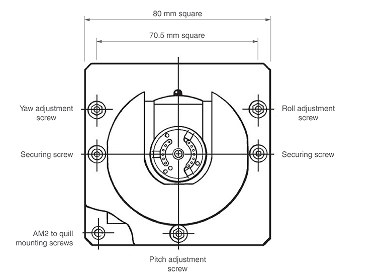
The AM2 adjustment module is designed to provide quick and accurate angular alignment of the PH10MQ PLUS motorised probe head with the axes of the CMM and Renishaw ACR3.
The AM2 consists of the adjuster plate, which is attached to the quill of the CMM, and a set of adjusters fitted to the flange of the head.
The probe head is fixed to the adjuster plate by a pair of captive screws.
The AM2 incorporates a quick release mechanism that allows the same probe head to be removed for storage and refitted without further alignment.
NOTE: If repeatability of position is required on re-attachment, only the securing screws should be released. Do not alter the other screws. This repeatability of position is normally sufficient for alignment with the autochange rack, but probes must be requalified for measurement.

Adjusting the AM2
A special tool is supplied, consisting of a concentric hexagon key and socket spanner. This should be located on the adjusters and locknuts recessed into the face of the head mounting flange.
NOTE: Springs are fitted under the adjuster locknuts to provide some preload during set up.
The procedure to use this tool is:
1. Slacken the locknut slightly using the outer part of the tool.
2. Set the adjuster using the inner part of the tool.
3. While holding the adjuster stationary with the inner part of the tool, tighten the locknut using the outer part of the tool:
Roll adjustment: Using the AM2 tool and the procedure given above, adjust the roll adjustment screw on the AM2.
Pitch adjustment: Using the AM2 tool and the procedure given above, adjust the pitch adjustment screw on the AM2.
Yaw adjustment: Using the AM2 tool and the procedure given above, adjust the yaw adjustment screw on the AM2.
4. Tighten the two securing screws.
NOTE: Tightening the securing screws could cause the roll, pitch or yaw alignment to change. It is therefore recommended that the alignments are checked after this procedure.