Encoders accelerate PCB impedance verification
Background
High-speed circuitry needs designers to predict the speed at which signals propagate along printed circuit board (PCB) tracks. Signal integrity needs to be maintained, and as the form factor of hand-held electronic devices diminishes, keeping PCB impedance within acceptable limits becomes an increasing challenge.
Volume manufacturing of high frequency electronic products requires high-performance PCB impedance measurement machinery capable of reliably verifying that actual production outcomes meet with calculated impedance targets.
Precision machine builder, Sam-Jeong Automation is using Renishaw's TONiC™ incremental encoder and tape scale system to deliver the speed, accuracy and repeatability required by its next generation PCB impedance measurement machine.
Printed circuit boards for complex high-frequency portable products, such as smart phones for example, must be manufactured to achieve individual track and circuit-wide impedance values specified at the design stage. Failure to do so can adversely affect signal integrity.
While the resistive force encountered by a DC signal transmitted along a PCB track is generally defined as resistance, impedance is a measurement of the resistive force encountered by an AC signal when it passes through a set of circuits that include resistors, capacitors and inductors. This impedance, also known as ‘characteristic impedance', is a resistive factor that must be taken into account when designing high-frequency signal boards. Accurate verification of PCB impedance is therefore vital, and the impact of product miniaturisation will only make it even more important.
In terms of physical size, smart phones in another five years' time are likely to be yet smaller; maybe 5 mm shorter, 5 mm narrower and another 1 mm thinner. Inside, multilayer motherboards will probably be a minimum of 12 layers deep. This continued miniaturisation makes designing for controlled impedance increasingly challenging. PCB track-widths will likely have to reduce, as will the distance between tracks in both horizontal and vertical planes and lower dielectric constant PCB substrates may have to be found, along with lower resistance copper (or similar) foils. Whatever the material composition and structure, the importance of ensuring PCB signal integrity and verifying true impedance levels will only increase.
In responding to the challenge, Sam-Jeong Automation, a South Korean provider of precision motion control solutions has applied its in-depth knowledge of electronic component manufacturing and testing to develop automated PCB impedance measurement machines capable of delivering the performance demanded by high volume consumer product manufacturers.
Challenge
In developing a board impedance measurement machine capable of automatically testing such ultra-fine PCB architectures, positional accuracy was a paramount concern for Sam-Jeong designers. Measurement probes would need to be able to locate an array of tightly distributed PCB test points without error.
Repeatability was an equally important factor, with the machine needing to compensate and adjust for minor divergence in (PCB) manufacturing. It also needed to be able to cope with changes in environmental conditions within the production area and the effects of thermal expansion.
Machine speed was another vital design criterium for the machine design. In fast-moving mass production environments, like that associated with smart phone manufacture, Sam-Jeong's machine would need to ensure production throughput was maximised and not hampered by the PCB impedance measurement process.

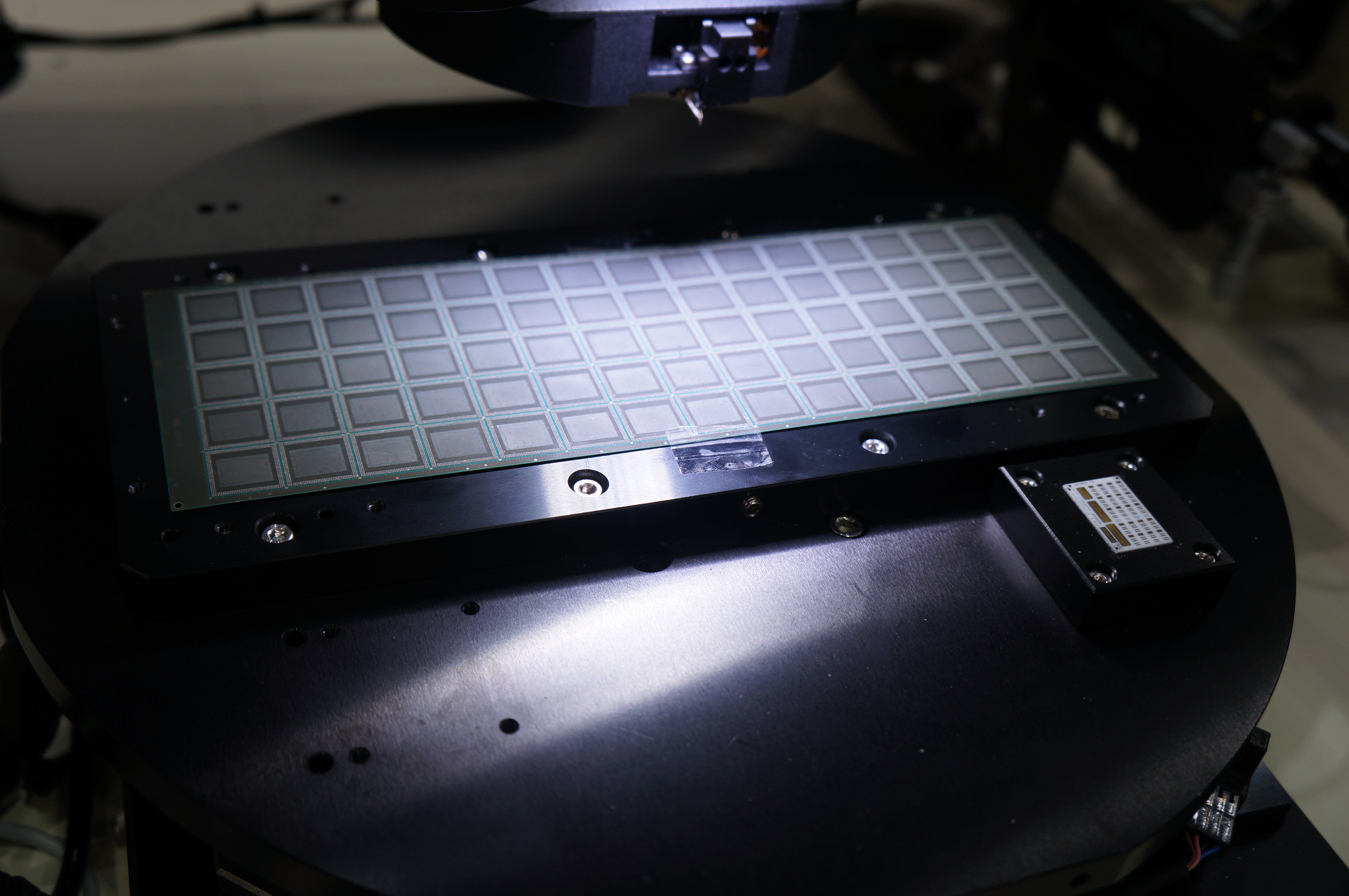
PCB under test
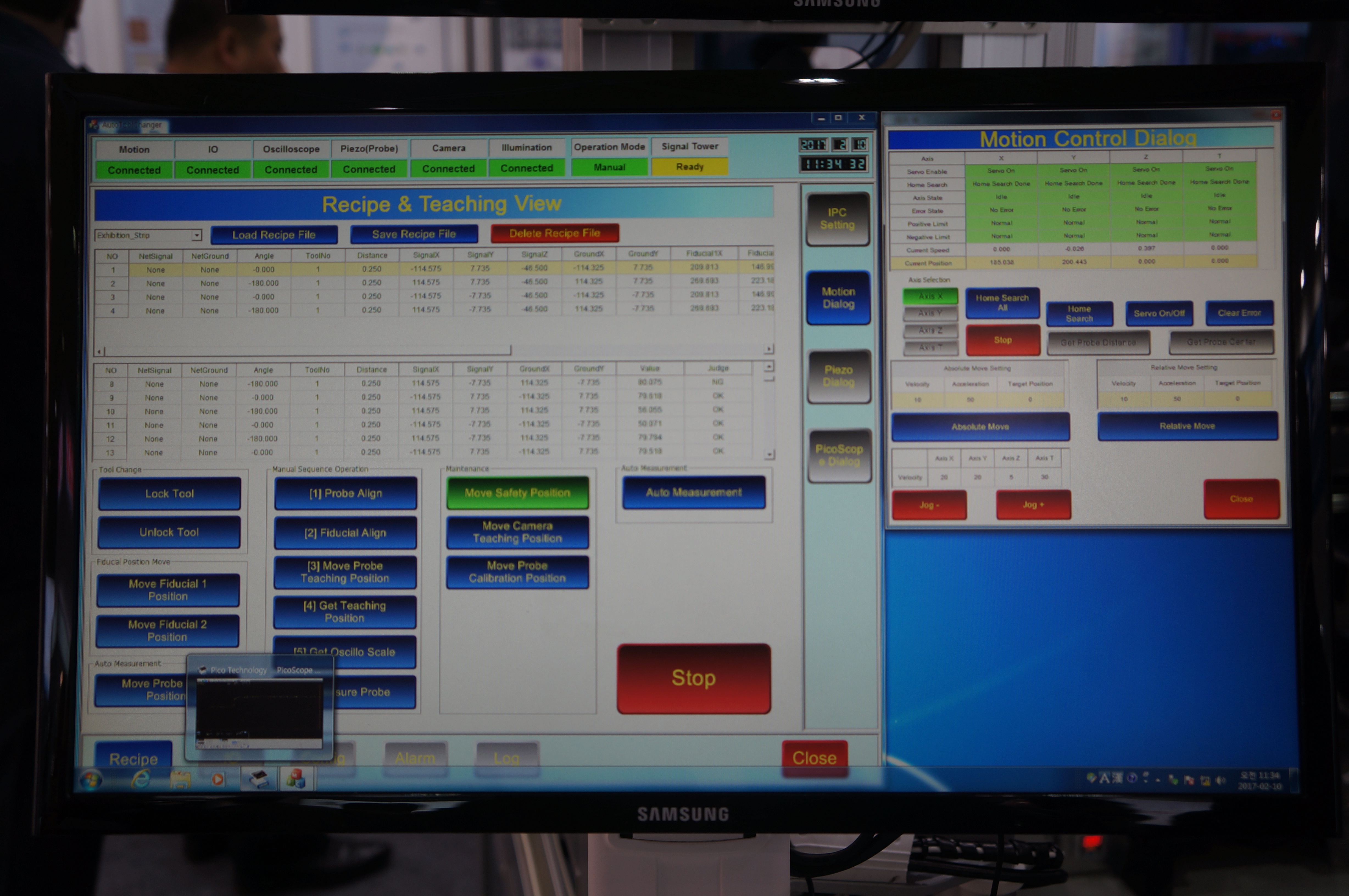
 System user interface
Solution
Sam-Jeong Automation's machine is based on a classic gantry-type design, with high-speed linear motors driving X- and Y-axes along pre-programmed paths to accurately position the impedance measurement probe onto the test points. Proprietary software is used to determine whether PCB impedance measurements fall within specification.
The PCBs under test are clamped on a rotating stage at the centre of the machine workbench and a high-resolution machine vision camera is used to identify and program the PCB test point locations.
Mr Yoo Hee-nok, Deputy General Manager, Sam-Jeong Automation explained the basic principle behind the impedance measurement:
“Impedance measurement machines like ours use the principle of time domain reflectometry or ‘TDR', which works in a similar way to radar. A pulse emitter sends a signal through a probe to the track for testing and if there is any discontinuity in the impedance, or any mismatch, then part of the signal is reflected back to the source.”
“TDR then measures of the voltage amplitude of the reflected signal to identify changes in impedance. Software determines the flight time from the reflection point to the emission point in order to be able to determine the location of the mismatch impedance change along the transmission path.”
To ensure the measurement probe's positional accuracy Sam-Jeong Automation chose to use Renishaw's TONiC™ incremental encoder readhead with RTLC linear tape scale and FASTRACK™ track system.
A super compact (35 mm x 13.5 mm x 10 mm) non-contact incremental encoder series, TONiC is designed to suit highly dynamic precision motion control systems. A range of innovative features brings higher accuracy, speed and greater reliability. It supports machine speeds up to 10 m/s and when combined with the external Ti signal interface offers resolutions via digital interpolation down to 1 nm.
To increase machine reliability and immunity to dust and dirt, the TONiC readheads also incorporate third-generation filtering optics tuned for low noise, and dynamic signal processing including auto gain and auto offset control. This results in a low sub-divisional error (±30 nm) ensuring smoother velocity control, improved scanning performance and increased positional stability.
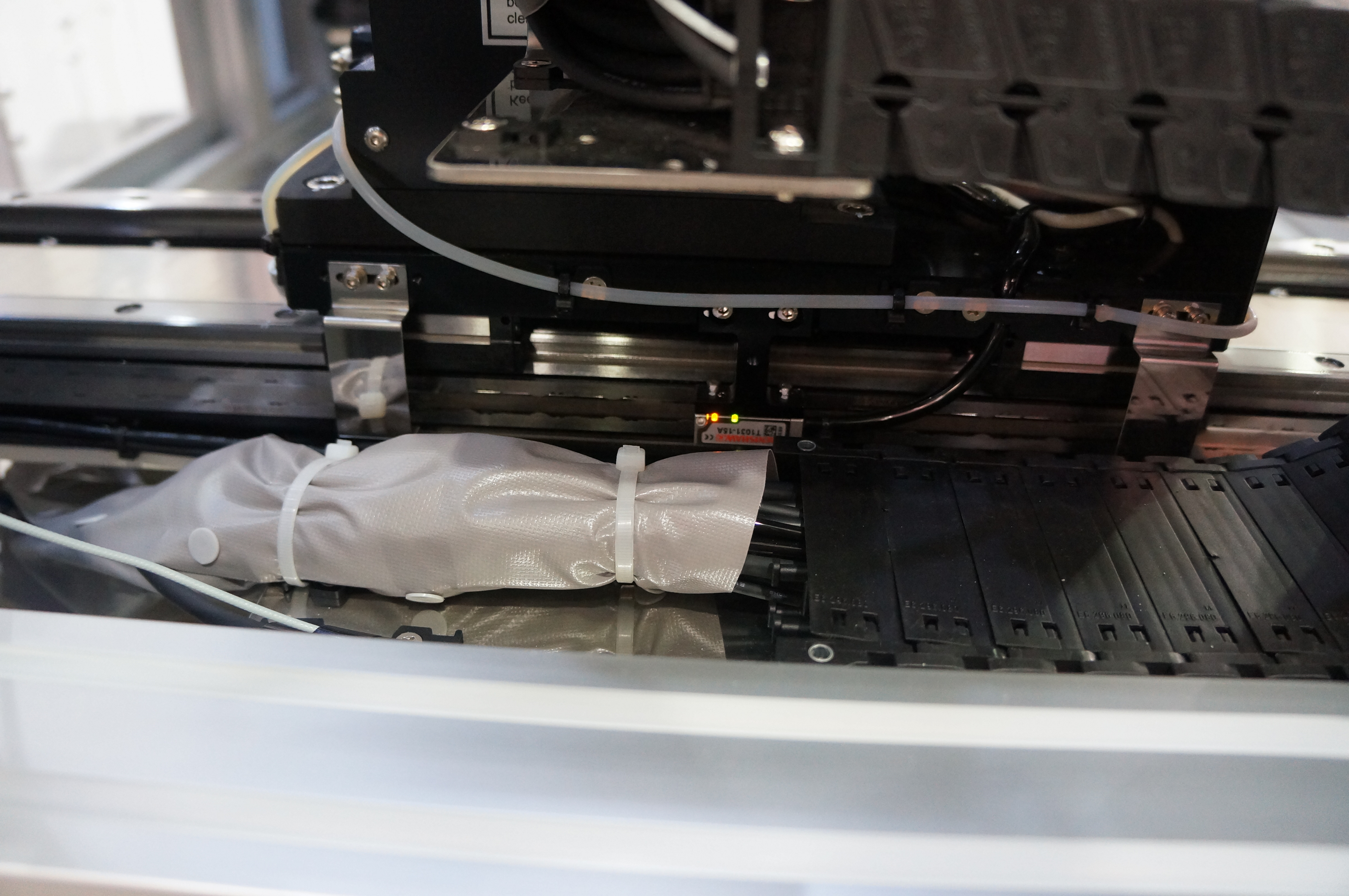
On the Sam-Jeong machine the RTLC low profile stainless steel tape scale and TONiC encoder readheads measure 500 mm of probe travel along both the X- and Y-axis. Importantly, the scale is held in place using FASTRACK, a rugged pair of miniature guide rails, as Mr Hee-nok explains:
“Since our machine gantry substrate is precision machined from aluminium, we had to guard against the prospect of thermal expansion adversely affecting the accuracy of the optical encoder system. By using the RTLC scale in conjunction with the FASTRACK scale carrier we addressed the problem.
By applying the encoder scale to the substrate using the scale carrier, it doesn't have to come into contact with any bonding agents or non-dry adhesives. This allows it to expand within its own expansion coefficient range. In effect it's almost ‘suspended' on the substrate.”
With the expansion coefficient of aluminium generally being above 20 µm/m/ºC and that for the RTLC scale being just 10.6 µm/m/ºC, the use of the FASTRACK guiderail enabled Sam-Jeong to successfully mitigate any effects of temperature change on encoder accuracy.
An additional benefit provided by using FASTRACK is convenience. In applications that require a machine to be broken down for transportation, the encoder scale is easily removed from the guiderails and quickly replaced, even when access is limited, ensuring downtime is minimised.
While the positioning accuracy and speed assured by the TONiC readhead was vitally important to the impedance measurement, Mr Hee-nok explained how repeatability was equally important as an enabler for controller parameter compensation to further improve overall machine performance.
“The machine needs to deliver a repeatable precision of ±1 µm. Precision designed BGA (ball grid array) boards for example can have gaps between solder balls as narrow as 50 µm, and we need to ensure precise positioning of the probe on the balls for every impedance measurement. TONiC's repeatable precision is at the measurement unit level, which massively increases the flexibility we have when we perform system optimisation including parameter compensation.”

TONiC encoder in-situ
Result
Sam-Jeong Automation has designed a next generation PCB impedance measurement machine that has been well received by customers. The accuracy and speed with which the machine is verifying board performance and diagnosing faults is helping to boost manufacturing throughput and reduce production losses. By harnessing state-of-the-art incremental encoder technology, the company has produced a machine fully capable of keeping pace with the rapid product miniaturisation expected in the future.
VIONiC™ encoders
The success of the TONiC encoder series has led Renishaw to develop its VIONiC encoder series. An ultra-high accuracy, all-in-one digital incremental encoder, VIONiC combines interpolation and digital signal processing inside the readhead, thereby removing the need for an external interface. Suiting both linear and rotary applications, VIONiC offers sub-divisional error of typically ±10 nm and resolutions down to 2.5 nm. An optional Advanced Diagnostic Tool (ADT) provides comprehensive feedback through an intuitive software interface.

