Navigation
Generic adaptor PCB
The generic adaptor PCB can be used to provide a quick and easy method of connection when performing a CMM retrofit with Renishaw's range of UCC controllers.
This PCB can be used when replacing any controller type as the CMM cables connect to screw terminals connectors.
The PCB supports the signals of up to 3 axes with the option of supporting analogue readheads with a plug-in interpolator PCB.
It is recommended that crimp ferrules are used to improve the reliability of the wire connection.
All interconnecting cables to the controller / SPA are provided.
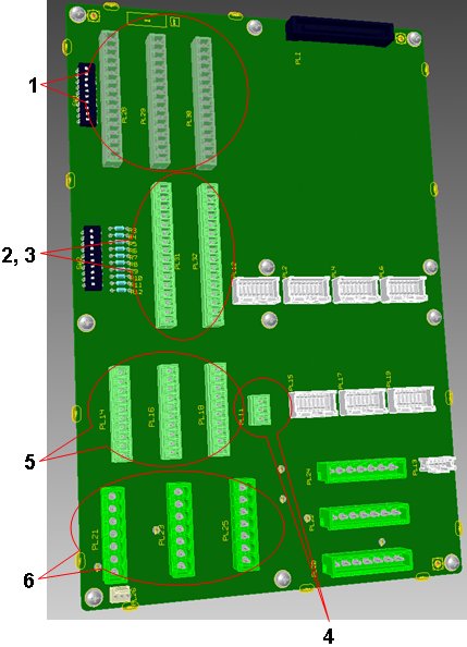
1. Readhead input
Table below shows the pin connections for standard RS422 and analogue read heads, unused inputs can be disabled via the disable switches as detailed on the readhead switch settings page.
Pin number | Digital readhead | Analogue readhead |
1 | 0 V supply | 0 V supply |
2 | 0 V sensing | 0 V sensing |
3 | +5 V supply | +5 V supply |
4 | +5 V sensing | +5 V sensing |
5 | -Readhead error | V ref |
6 | -Reference mark | -Reference mark |
7 | +Reference mark* | +Reference mark* |
8 | Limit switch Q** | Limit switch Q |
9 | -B signal | -Cos |
10 | +B signal | +Cos* |
11 | Limit switch P | Limit switch P |
12 | -A signal | -Sin |
13 | +A signal | +Sin* |
14 | Inner screen | Inner screen |
15 | Screen | Screen |
Mating part | P-CA79-0008 | P-CA79-0008 |
* Connect single ended analogue signals to positive inputs only.
** Renishaw controllers capable of supporting both single and dual limit-switch RG22 readheads. The electronic circuits can interface either type without any intervention but the correct type must be set in the machine "ini" file. If dual limit types are fitted pin 11 functions as the second limit switch. If single types are fitted then pin 8 becomes the +Error signal.
2. CMM I/O pinout
Table below shows the CMM I/O pinouts. The machine I/O can be configured using the disable switches detailed in the Generic I/O switch settings page.
Multiple +24 V and 0 V connections are provided for easy wiring.
NOTE: Series wired limit switches should be connected to the crash input on the CMM I/O connector.
Pin number | Description |
1 | +24 V dc |
2 | Z brake |
3 | Z brake release button |
4 | CMM declutch |
5 | 0V supply |
6 | +24 V dc |
7 | Energise air solenoid |
8 | Crash switch |
9 | 0 V supply |
10 | +24 V dc |
11 | Output 0 |
12 | Input 0 |
13 | 0 V supply |
14 | Low air |
15 | 0 V supply |
16 | Screen |
Mating part | P-CN01-0014 |
3. Limit switch inputs
The table below details the connections for limit switches. Individual limit switches are to be configured using the disable switches detailed in the Generic I/O switch settings page.
NOTE: Series wired limit switches should be connected to the crash input on the CMM I/O connector.
Pin number | Description |
1 | +24 V dc |
2 | +24 V dc |
3 | +X inner limit |
4 | -X inner limit |
5 | 0 V supply |
6 | +24 V dc |
7 | +Y inner limit |
8 | -Y inner limit |
9 | 0 V supply |
10 | +24 V dc |
11 | +Z inner limit |
12 | -Z inner limit |
13 | 0 V supply |
14 | +24 V dc |
15 | Screen |
16 | Screen |
Mating part | P-CN01-0014 |
4. Emergency stop switch
The external emergency stop switch pinout is shown below.
Pin number | Description |
1 | E-STOP A |
2 | E-STOP B |
3 | Screen |
Mating part | P-CN25-0008 |
NOTE: If no external E-STOP switch is used pins 1 and 2 must be connected together.
5. Motor encoder inputs
RS422 digital motor encoders can be connected as detailed in the table below.
Pin number | Description |
1 | 0 V supply |
2 | -Reference mark |
3 | -B signal |
4 | -A signal |
5 | +5 V supply |
6 | +Reference mark |
7 | + B signal |
8 | + A signal |
9 | Inner screen |
10 | Screen |
Mating part | P-CN25-1053 |
6. DC motor connection
The Renishaw retrofit standard DC motor connections as shown in the table below.
Pin number | Description |
1 | +ve Motor connection |
2 | Reserved |
3 | -ve Motor connection |
4 | Motor screen |
5 | +ve Tacho input |
6 | -ve Tacho input |
7 | Tacho screen |
Mating part | P-CN24-0046 |