Navigation
Installation options
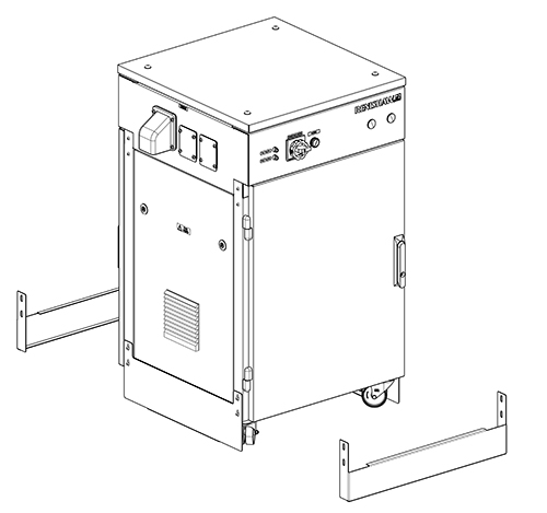
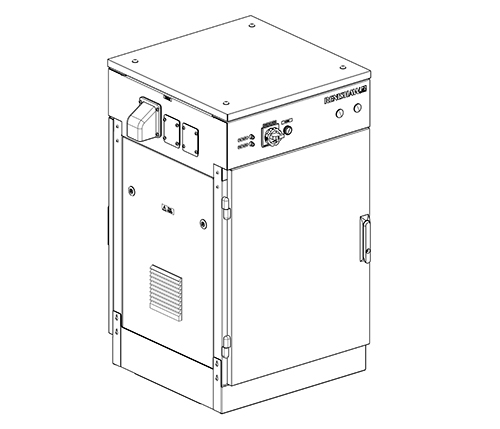
The cabinet must be restrained from toppling.
The preferred option is to use floor mounting fixings to secure the cabinet to the floor. The kick plates supplied in the cabinet kit should be secured to the floor. Pull force on floor fixing must be a minimum of 1 KN.
If cabinet cannot be fixed to the floor using kick plates then the suitable restraints should be used to remove the risk of the cabinet toppling.
Attaching bulkhead to cabinet
The bulkhead can be attached using the 4 × fitting screws supplied.
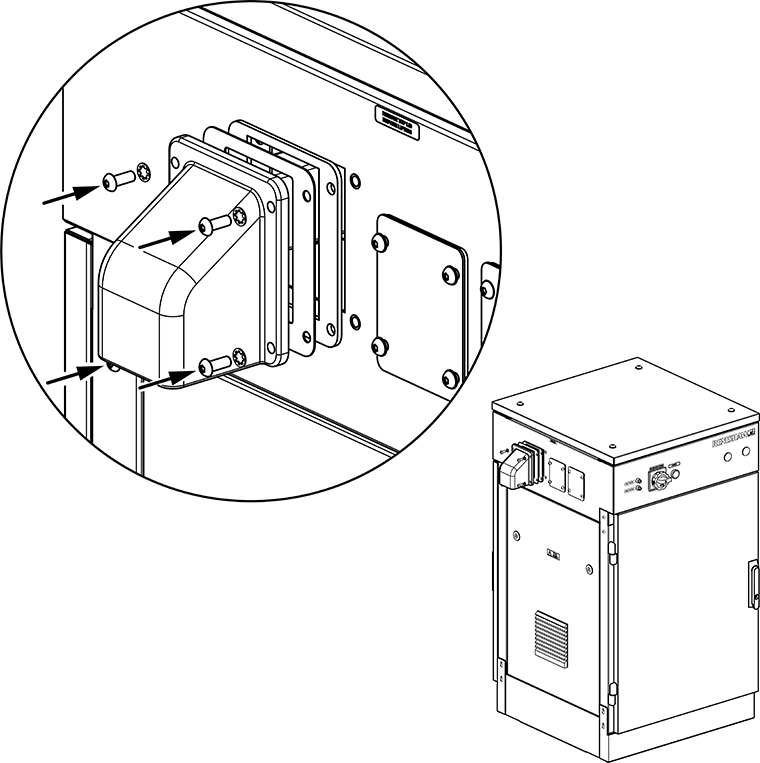
Tighten the screws using a 4 mm hex wrench to a maximum torque of 2 Nm.
Kick plate installation overview
Positioning holes for ground fixing
The cabinet should be fixed to the ground as part of the installation. The diagram below shows the location of the required holes to allow the use of floor studs.
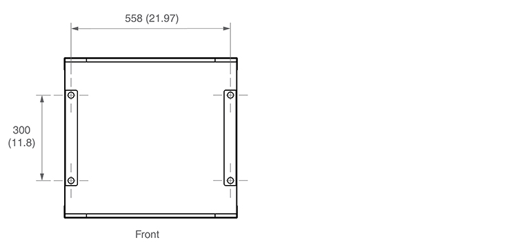
The type and size of studs used is dependent on the requirements of the installation site. These details should be discussed prior to installation.
1. Fix the left-hand side plate to the floor using anchors.
2. Roll the cabinet into position.
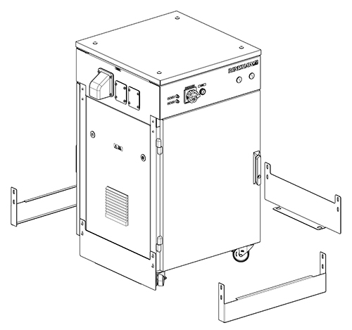
3. Fix the right-hand side plate to the floor using anchors.
4. Fix the cabinet base to the side plates.
5. Once attached, fix the front and rear panels in place.
NOTE: If desired the cabinet can be re-positioned and re-installed by a single engineer with no lifting equipment. Please contact the installer to arrange reposition of the cabinet if required.