Navigation
Hardware configuration
CAUTION: Connection to the protective bonding circuit: Provision for connecting the complete machine to the protective ground (earthing) is the responsibility of the manufacturer or equipment installer.
Isolation: The SPA2-2 is isolated by removing the mains connector. It is the responsibility of the equipment installer or user to fit additional means of isolation if indicated by risk assessment.
Earth fault / residual current protection: It is the responsibility of the machine manufacturer or product installer to ensure an adequate level of protection for the complete machine installation.
Installation of motor connection cards
NOTE: It is assumed that this is the first installation process and that no mains supply is connected to the unit.
1. Remove the SPA2-2 from its transit packaging.
2. Place the SPA2-2 on a firm flat surface, with the front of the unit placed on the surface and the rear of the unit facing upward.
3. Remove the necessary connector protection covers from the rear of the SPA2-2. These are retained by spring clips and can be simply pulled out using the hole in the centre.
4. Remove a motor connection card from its packaging.
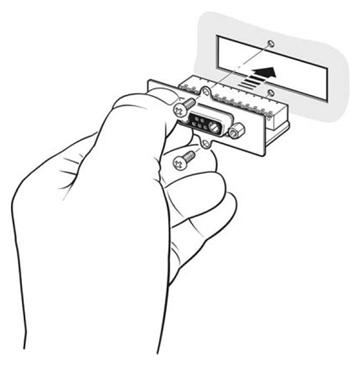
5. Align the motor connection card with the necessary axis connection position on the rear of the SPA2-2 and press the connector firmly into position (see below).
CAUTION: It is essential that each axis connector location should have either a connector blanking plate or a motor connector in place before the SPA2-2 is powered up.
NOTE: The motor connection card must be inserted into the SPA2-2 until its mounting plate is in contact with the rear panel of the SPA2-2.

6. Using the screws provided, secure the motor connection card to the SPA2-2 rear panel.
7. Repeat steps 3 through 6 until all required motor connection cards are fitted.
8. If a 4th axis interface card is to be fitted proceed to the 'Installation of 4th axis card' section, or if a REVO connector card is to be fitted then proceed to the 'Installation of REVO™ connector card' section. Otherwise the unit can now be installed.
Installation of 4th axis card
1. Place the SPA2-2 on a firm flat surface, with the base of the unit placed on the surface and the rear of the unit facing towards you.
2. Remove the four plastic bungs from the front of the side panels.
3. Remove the lid of the SPA2-2 enclosure by removing the three screws at the top of the rear panel and then lever the rear of the top panel upwards by inserting a screwdriver into the semi-circular cut out in the top of the rear panel. When the top panel is clear of the rear panel, pull the top panel towards you to release the front clips. The top panel can now be lifted off. Retain the fixings.
4. Remove the necessary connector protection cover from the rear of the SPA2-2, this is retained by a spring and can simply be pushed out.
5. Remove the 4th axis card from its packaging.
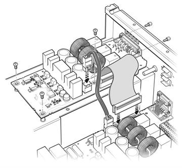
6. Attach the communication and power cables that are supplied with the 4th axis option card to the motherboard (see below).
NOTE: If this interface card is being fitted to a 6-axis SPA2-2 then the communication and power cables will have already been installed on the lower motherboard. In this instance the cables supplied with the kit can be discarded.
7. Position the 4th axis card into its correct location, as shown below.

8. Locate the 4th axis card onto the pillar mounts using the M3 screws supplied. Do not tighten these screws.
9. Using the jackscrews supplied, secure the 4th axis card connector through the location hole in the rear panel of the SPA2-2. Tighten the jackscrews (taking care not to overtighten) and then tighten the screws fitted in step 7.
10. Fit the communication cable attached to the SPA2-2 motherboard to the 4th axis interface card, as shown in the diagram above.
11. Fit the voltage supply cable loom from the SPA2-2 to the 4th axis option card, as shown in the diagram above.
12. Refit the lid by reversing the procedure in step 3 and replace the plastic bungs.