Navigation
Connector pin-outs
PICS input connector
The PICS input connector is a 9 pin ‘D' type socket. The pin numbers are illustrated and their functions are shown in table.

Pin number | Description | Pin number | Description |
|---|---|---|---|
1 | STOP | 6 | STOP +5 V pull-up |
2 | PPOFF | 7 | PDAMP |
3 | Ground (0 V) | 8 | LEDOFF |
4 | LED anode | 9 | Probe signal ground |
5 | Probe signal input | Shell | Screen |
PICS output connector
The PICS output connector is a 9 pin ‘D' type plug. The pin numbers are illustrated and their functions are shown in the table.

Pin number | Description | Pin number | Description |
|---|---|---|---|
1 | STOP | 6 | HALT |
2 | PPOFF | 7 | PDAMP |
3 | Ground (0 V) | 8 | LEDOFF |
4 | Reserved | 9 | Not used |
5 | SYNC | Shell | Screen |
SSR output connector
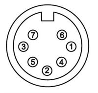
The solid state relay output connector is a 7 pin DIN socket. The pin numbers are illustrated and their functions are shown in the table.
The SSR relay is rated to 30 Vac / dc (limited by the DIN connector) at 50 mA (limited by the relay).
Raw probe output connector (view on rear panel)

Pin number | Description | Pin number | Description |
|---|---|---|---|
1 | Not used | 5 | SSR 2 |
2 | Screen | 6 | Not used |
3 | Not used | 7 | Not used |
4 | SSR 1 | Shell | Screen |
Stylus change rack (SCR) output connector
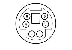
The SCR200 stylus change rack is connected to the PI 200-3 via a 6-pin miniature DIN socket. The pin numbers are illustrated and their functions are shown in the table.
SCR200 output connector (view on rear panel)

Pin number | Description | Pin number | Description |
|---|---|---|---|
1 | Reset | 4 | +5 V |
2 | Fault | 5 | Ground (0 V) |
3 | Inhibit | 6 | Not used |
Remote reset
There are two methods of connection to a remote push button that will achieve the same effect as the RESET button on the front panel of the PI 200-3 interface. This may be useful if manual stylus changing is frequent, or if the PI 200-3 is difficult for the operator to access.
A momentary action push button or switch may be connected to pins 1 and 5 on the SCR200 miniature DIN connector on the rear panel. If the connector is already in use for connection of a SCR200 stylus change rack, a dual rack cable type PL97 may be used to provide an additional connector.
Alternatively, the button may be directly wired to the PPOFF and ground (0 V) pins (pins 2 and 3) on either of the PICS connectors on the rear panel of the PI 200-3.