Navigation
Appendix
Installing / commissioning brushless motors
Compatibility / restrictions
- Brushless motor functionality is only available in UCCsuite 5.3 or later
- Brushless motor functionality is only available when using a UCC BI and SPA2-2
- The software does not support Hall Effect sensors for commutation. However, it is likely that these systems can still be retrofitted by using the scale feedback or a motor encoder.
- If a brake is fitted to an axis driven by a brushless motor the brake must have a small amount of compliance to allow the commutation search procedure to move the motor by a small amount (between 0.1 mm and 0.5 mm but is dependent on motor specification).
- Rotary brushless motors must have an encoder on the motor, otherwise commutation angle errors will occur after a few revolutions. The resolution of the rotary encoder must be given exactly as the original motor specification, otherwise commutation angle errors will occur after a few revolutions.
Encoder cable connection
For linear brushless motors the axis scale cables must be connected to the UCC BI scale connector. The UCC BI will transmit the scale feedback information to the SPA2-2 over the SPA2-2 comms connection.
For rotary brushless motors the motor encoder cables must be connected to the encoder connectors on the SPA2-2.
Commissioning sequence
Most of the commissioning sequence is the same as conventional brushed motors, the differences are detailed in the following section.
SPA configuration
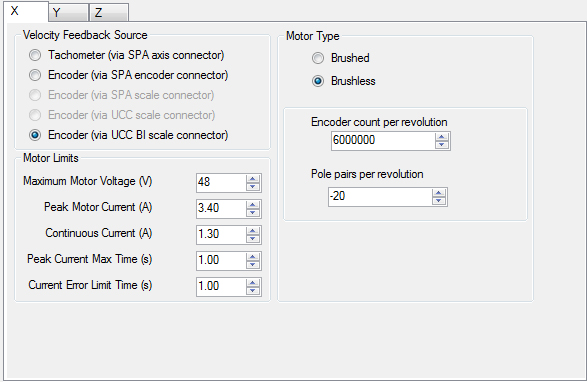
The SPA configuration screen has additional parameters that are only configurable when ‘motor type' is set to ‘brushless'.

For linear brushless motor drives
- Select “Encoder (via UCC BI scale connector)” as the velocity feedback source
- Select “Brushless” for motor type
- Peak current / voltage follows the motor specification
- See below for an explanation of encoder count per revolution and pole pairs per revolution
For rotary brushless motor drives
- Select “Encoder (via SPA encoder connector)” as the velocity feedback source
- Select “Brushless” for motor type
- Peak current / voltage follows the motor specification
- See below for an explanation of encoder count per revolution and pole pairs per revolution
NOTE: the term ‘revolution' is applicable to both rotary and linear motors as a linear motor can be envisaged as a rotary motor that has been rolled out flat.
Encoder counts per revolution:
This is the number of encoder counts seen when the motor travels past the number of pole pairs specified by ‘Pole pairs per revolution'.
Pole pairs per revolution:
This parameter sets the number of pole pairs in one revolution of the motor.
A linear brushless motor has north and south poles laid out alternately:
Number of pole pairs = total number of poles / 2.
The above image contains 5 pole pairs.
It is unlikely that the number of pole pairs in a rotary brushless motor can be determined without opening the motor casing, therefore the motor manufacturer's specification must be used.
Unless the polarity of “pole pairs per revolution” is known from an identical machine it can only be determined by using the ‘configure motor, scale and feedback polarity' action in the machine commissioning sequence.
Determining “encoder counts per revolution” for rotary motors:
For rotary brushless motors the accuracy of this value is critical so it must come from the motor manufacturer's specification. It would very difficult to count the exact number of counts per revolution and any error would be compounded over multiple revolutions.
Determining “encoder counts per revolution” for linear motors:

If ‘length per pole pair' is known from the motor specification it can be used to calculate encoder counts per revolution.
Counts per pole pair = length per pole pair / scale resolution
Encoder counts per revolution = number of pole pairs X counts per pole pair
For example, if the manufacturer's motor specification states that the length per pole pair is 30 mm and the resolution of the scale is 0.0001 mm then counts per pole pair is 30 / 0.0001 = 300000. As the number of pole pairs for this length is 1, encoder counts per revolution will also be 300000.
If the motor specification for “length per pole pair” cannot be obtained it can be calculated for linear motors by measuring the length of as many pole pairs as possible, ideally the distance from the start of the first pole to the end of the last pole. A small amount of measurement error (i.e. 1 mm or 2 mm) is acceptable if the measurement is over many pole pairs.

Encoder counts per revolution = total length of pole pairs / scale resolution
For example, if the total length of pole pairs is 965 mm and the resolution of the scale is 0.0001 mm then encoder counts per revolution = 965 / 0.0001 = 9650000. This value is proportional to ‘pole pairs per revolution', which in this example is 5.
Configure motor, scale and feedback polarity (battery box test)
The battery box test for a brushed motor finds:
- Motor polarity
- Scale polarity
- Scale increment
- Motor feedback polarity
The battery box test for brushless motor will also find:
- The polarity of “pole pairs per revolution”. The polarity of “pole pairs per revolution” is effectively the polarity of the commutation angle, if the polarity is incorrect the commutation angle will be updated incorrectly as the axis moves - this means that the axis will not move smoothly or might not move at all.
NOTE: The battery box test will release the axis brakes. Typically, linear motors have low static friction, so when the brakes are released the axes could move if the CMM is not level or if some force is being exerted by the energy chains. So that this movement is not confused with battery box motion it is recommended to manually release the brakes and let the axes settle before re-applying the brakes and starting the battery box test.
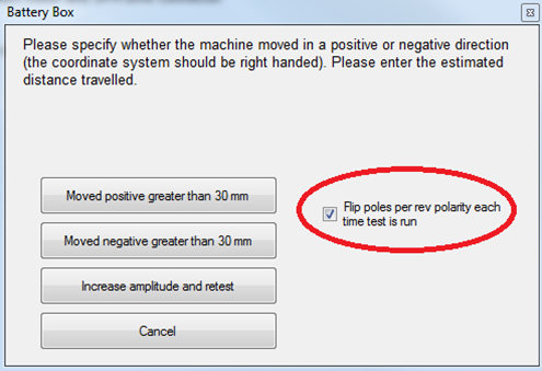
Running the battery box test is very similar to commissioning conventional brushed motor machines. The difference is that the dialog box that is displayed to the user after each run completes now has a checkbox called “Flip poles per rev polarity each time the test is run”. If this box is checked, the polarity of “number of pole pairs” will be inverted on the next run.

The basic technique is to look for smooth machine motion. Even if the distance moved is small (it needs to be longer than the length of one pole pair), smooth machine motion means the sign of the commutation angle is correct.
- Move to the middle of the machine volume
- Release brakes (if fitted) to allow the axis to settle then re-apply
- Keep your hand on the E-STOP whilst running
- The tests start with “Flip poles per rev polarity each time test is run” checked
- Perform the battery box test
- The test will take longer than the brushed motor battery box test because the commutation angles need to be found first
- If the axis “jerks” a small distance this is not smooth machine motion, click on “increase amplitude and retest”
- When the axis moves over a small distance smoothly, it means the sign of commutation angle is correct. Uncheck “flip poles per rev polarity each time test is run” and carry on until the axis moves more than 30 mm.
Storing commutation offset angles
If there is concern that the commutation angle finding routine performed during "configure for motion" is giving inconsistent results it is possible to configure the system to apply a known (i.e. previously found) commutation angle after the axes have been homed. UCCassist-2 does not provide a commissioning interface for this functionality so the user must contact CMM support for further information.