Navigation
UCC T3-2 introduction
The UCC T3-2 is the latest generation Renishaw CMM controller product range. It supports the complete range of Renishaw two wire touch-trigger probes along with the high performance TP200 probe.

Key | Description |
1 | Machine motors |
2 | Machine scales and readheads |
3 | Probe head - manual or fixed - connects to the UCC T3-2 via the machine cabling |
4 | UCCassist-2 commissioning software and application software |
5 | UCC T3-2 and power amplifier SPA3-2 - these connect to the machine cabling |
6 | MCU joystick - MCUlite-2, MCU5-2 or MCU W-2 - connects to SPA3-2 |
7 | PC - connects to UCC T3-2 via an ethernet cable |
The UCC T3-2 is a controller in a 19 inch rack-mountable enclosure. It is coupled to the CMM host computer by an ethernet link and to the CMM via external cable interface connectors.
The UCC T3-2 controller in conjunction with the SPA3-2 has the capability of:
- controlling three axes of a CMM (accepting digital readhead signals and generating three axes of motor drive signals)
- accepting input signals from emergency stop, air pressure, crash detector, digital SPA, amplifier faults and all axis inner and outer travel limit switches
- accepting two uncommitted general purpose input signals and generating one uncommitted general purpose output signal via SPA3-2
- directly supporting the TP1, TP2, TP6, TP20 and TP200 touch-trigger probes
- providing a +24 V supply for use by the CMM switches
- supporting the MCUlite-2, MCU5-2 and MCU W-2 joysticks
This guide gives information on physical installation, system connections and communications, as well as assistance in fault finding during the installation of the UCC T3-2.
WARNING: UCC T3-2 is not compatible with PH9, PH10, PHS, PH20 and REVO systems. No attempt should be made to connect these system components to the UCC T3-2 as this will result in damage to the product or attached equipment.
Please use this guide in conjunction with the SPA3-2 and PICS user's guide in order to fully understand the system's features, capabilities and operation.
The UCC T3-2 does not support TP7.
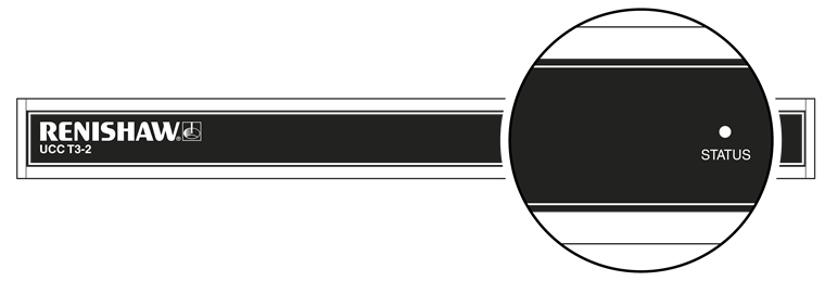
Front panel layout

Rear panel layout

Key | Description | Connector polarity |
1 | PICS | SOCKET |
2 | Ethernet communications connector to CMM computer | SOCKET |
3 | Reset button / IP configure button | |
4 | Reserved - do not connect | |
5 | SCR200 rack input (TP200) | SOCKET |
6 | RJ45 connector to SPA3-2 | SOCKET |
7 | RJ45 connector to second SPA3-2 | SOCKET |
8 | Reserved | |
9 | Reserved | |
10 | Equipotential bond point | BOLT |
11 | DC power jack 24 V | SOCKET |