Navigation
UCC - SPA (RJ45 socket)
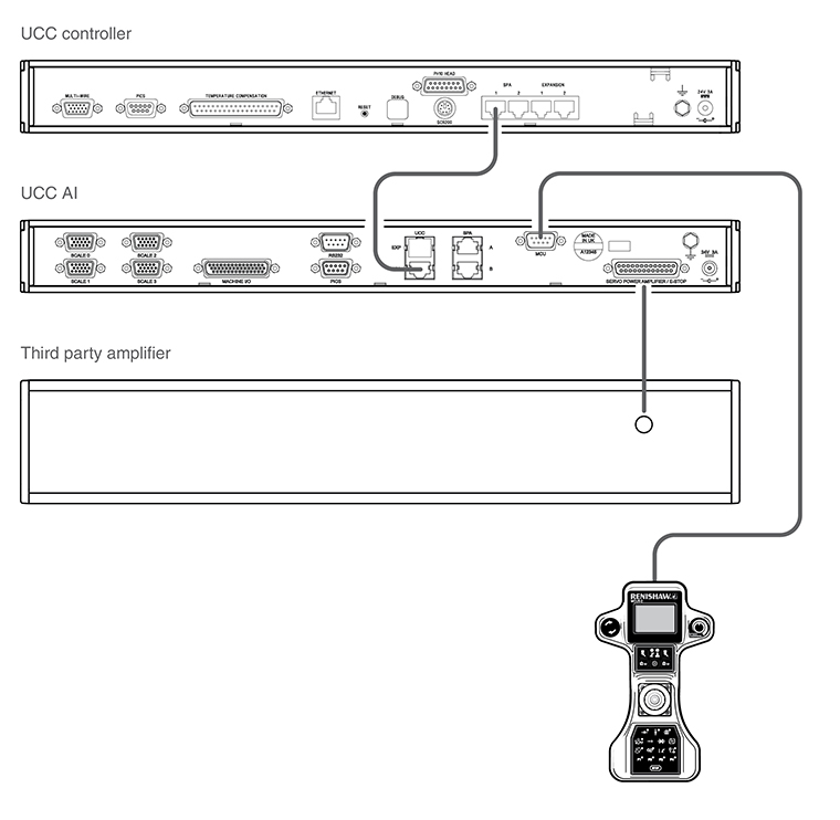
3 and 4-axis UCC AI interconnection
The UCC AI should be connected from the UCC - SPA port to the UCC controller (SPA port) using the RJ45 cable (Renishaw part number P-CA40-0040) provided in the UCC AI kit.
If the provided RJ45 cable is not used then the cable should be no longer than 300 mm in length, CAT 5E and shielded.
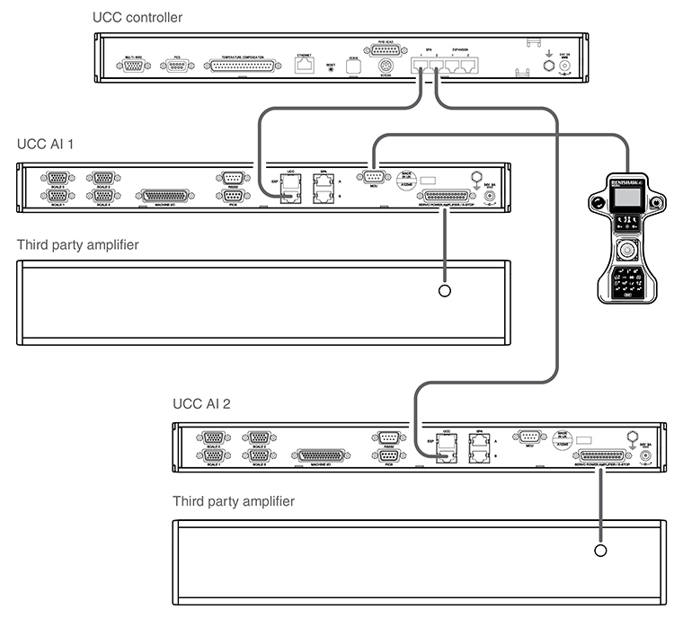
4 and 5-axis dual UCC AI interconnection
Dual UCC AI installations may require an E-STOP cable. This will depend on the E-STOP linkage between the UCC AI and third party amplifiers. However, the E-STOP tripped input on both UCC AIs is monitored.
NOTE: MCU, RS232, PICS, enable air solenoid, de-clutch, low air pressure and crash should be connected to UCC AI 1.
NOTE: The signals, 'amps OK', 'contactor', 'enable amps' and 'contactor feedback' on the UCC AI 1 should be connected to the 3rd party SPA associated with UCC AI 1, and these signals on UCC AI 2 should be connected to the 3rd party SPA associated with UCC AI 2.