Navigation
Automatic operation
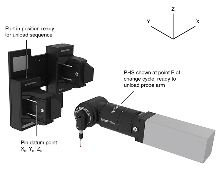
This section gives a suggested method for datuming an ACR2 autochange rack port and the recommended CMM movements for change cycles using that datum position.
Port datum procedure
This method allows datuming of each ACR2 port by taking probing points on one of the location pins.
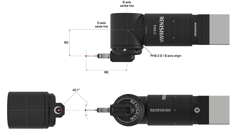
1. Qualify the PHS and probe combination as shown below.
NOTE: The probe tip must be qualified before the port can be datumed.
A typical probe assembly suitable for port datuming would be:
- HA8 probe arm
- TP2 probe
- PS17R 20 mm stylus
Nominal offset values for this probe assembly are:
- RD 72 mm
- RE 104 mm
The values RD and RE should be established to within ±0.1 mm by the probe qualification procedure.
NOTE: The angular orientation of the D and E axes required for port datuming (D 0°, E 0°). The probe tip should be aligned to the axis origins to within 0.1°.
ACR2 port datum procedure:
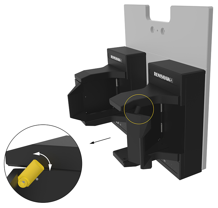
2. Position the ACR2 port in the lower latched position.
NOTE: To manually move between upper and lower positions, the two port pins must be pushed to the left to disengage the motion locks.
3. Lift the lid retaining clip up to hold the latch in the open position.
Port in lower latch position:
Lifting the latch retaining clip:
ACR2 port datuming procedure:
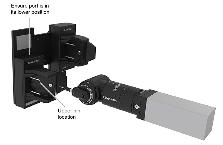
4. Take four points around the full diameter of the upper location pin in the ZX plane (assuming the rack is oriented to the CMM axes as shown on this page).
5. Use the four points to create a circle.
6. Use the centre point of the circle as the coordinates for the pin datum in the X and Z axes, XP and ZP.
7. Take one point on the end of the upper location pin in the Y-axis and use it as the coordinate for the pin datum in the Y-axis, YP.
8. Push the lid forward to release the retaining clip.
Pin datum position:
9. Offset the position XP, YP, ZP to the PHS D/E axis origin as shown below. Use this point XD, YD, ZD as the pin datum point.
XD = XP – RD
YD = YP + RE
ZD = ZP
Change cycles
To change probe arms automatically using the ACR2, the CMM must be programmed to complete a series of movements using the positions given in this section. When manually loading the arm into the autochange rack, care must be taken to ensure that the port is locked in the uppermost position.
The co-ordinates of the positions given in this section are relative to the coordinate system defined on the pin datum point XD, YD, ZD calculated in the port datum procedure.
Change cycle:
NOTE: D and E axes in correct orientation for change cycle (D0, E-90).
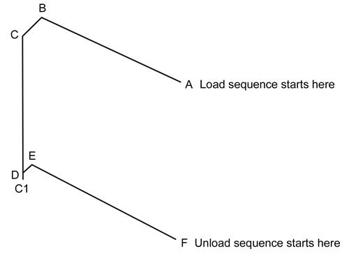
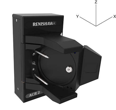
This drawing shows the axis orientation of the coordinate system used in the automatic change cycles given in this guide.
Axis orientation:
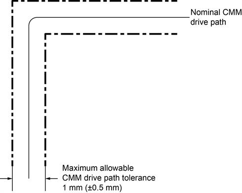
This diagram shows the maximum tolerance acceptable on the CMM drive path during the automatic change cycle.
Nominal CMM drive path:
PHS axis origin position relative to pin datum point XD, YD, ZD
This table gives co-ordinates for the points in the automatic change cycle relative to the pin datum point XD, YD, ZD calculated in step 8 of the port datum procedure.
Point | X | Y | Z |
|---|---|---|---|
A | +74 | -135.5 | +68.5 |
B | +74 | +14.5 | +68.5 |
C | +50 | +14.5 | +68.5 |
C1 | +50 | +14.5 | -35.5 |
D | +50 | +14.5 | -31.5 |
E | +53.5 | +14.5 | -31.5 |
+53.5 | -135.5 | -31.5 |
Moves in automatic change cycle
This table gives incremental values for the moves between points in the automatic change cycle.
Move | Axis | Incremental value | Function |
|---|---|---|---|
A to B | Y | +150 | PHS moves in (or out of) port without probe arm loaded |
B to C | X | -24 | PHS latches (or unlatches) port with probe arm unlocked |
C to C1 | Z | -104 | Arm locking move (load cycle only) |
D to C | Z | +100 | Arm unlocking move (unload cycle only) |
C1 to D | Z | +4 | Locking mechanism backoff (load cycle only) |
D to E | X | +3.5 | PHS latches (or unlatches) port with probe arm locked |
E to F | Y | -150 | PHS moves in (or out of) port with probe arm loaded |
Unloading a probe arm
- Recall the pin datum XD, YD, ZD set in step 8 of the port datum procedure
- The PHS should have a probe arm fitted
- Ensure the PHS is oriented into the correct position to enter the port (D 0°, E -90°)
Position relative to pin datum XD, YD, ZD:
X‑axis | Y‑axis | Z‑axis | Point | Description |
|---|---|---|---|---|
+53.5 | -135.5 | -31.5 | F | Stand off position. Head is in front of port and has probe arm fitted. Head is oriented to D 0°, E -90°. |
-114 | Transit stage PHS contacts the ACR2 port lid. This may cause a probe trigger, so the probing system should be disabled before reaching this point. | |||
-20 | Transit stage Probe arm engages port location pins. Renishaw recommend that servo control of the head axes should be switched off at this point. NOTE: Remove only 24 V servo power from the head. Do not remove logic power from the head as this will cause head position loss. | |||
+53.5 | +14.5 | -31.5 | E | PHS fully located in ACR2 port |
+50 | +14.5 | -31.5 | D | ACR2 ready to activate unlock mechanism |
+50 | +14.5 | +68.5 | C | Probe arm unlocked from PHS head |
+74 | +14.5 | +68.5 | B | Move PHS head clear of probe arm |
-20 | Transit stage Servo control of the head should be re-enabled. Note that the position of the head may have changed under gravity and that the head should be held in its current position before returning to the previous orientation. | |||
-114 | Transit stage PHS clears the ACR2 port lid. | |||
+74 | -135.5 | +68.5 | A | Stand off position Head is in front of port with no probe arm fitted. |
Loading a probe arm
- Recall the pin datum XD, YD, ZD set in step 8 of the port datum procedure
- The PHS should not have a probe arm fitted
- Ensure the PHS is oriented into the correct position to enter the port (D 0°, E -90°)
Position relative to pin datum XD, YD, ZD:
X‑axis | Y‑axis | Z‑axis | Point | Description |
|---|---|---|---|---|
+74 | -135.5 | +68.5 | A | Stand off position. Head is in front of port with no probe arm fitted. Head is oriented to D 0°, E -90°. |
-114 | Transit stage PHS contacts the ACR2 port lid. | |||
-20 | Transit stage Renishaw recommend that servo control of the head axes should be switched off at this point. NOTE: Remove only 24 V servo power from the head. Do not remove logic power from the head as this will cause head position loss. | |||
+74 | +14.5 | +68.5 | B | PHS located in ACR2 port clear of probe arm |
+50 | +14.5 | +68.5 | C | Locate PHS head onto probe arm ready for lock sequence |
+50 | +14.5 | -35.5 | C1 | Lock probe arm to PHS head |
+50 | +14.5 | -31.5 | D | Move probe arm lock mechanism to normal position |
+53.5 | +14.5 | -31.5 | E | Move ACR2 port into fully locked position |
-20 | Transit stage Probe arm begins to clear port location pins. Servo control of the head should be re-enabled. | |||
-114 | Transit stage PHS clears the ACR2 port lid. Probing system can now be enabled. Note that the position of the head may have changed under gravity and that the head should be held in its current position before returning to the previous orientation. | |||
+53.5 | -135.5 | -31.5 | F | Stand off position. Head is in front of port with new probe arm fitted. |