Navigation
Autochange software
Commands and responses
Code | As a command to ACC2-3 | As a response from ACC2-3 |
|---|---|---|
A | Change cycle enable | Possible responses to rack status request |
B | - | Possible responses to rack status request |
C | Rack status request | Possible responses to rack status request |
D | Datum mode select | Possible responses to rack status request |
E | - | Possible responses to rack status request |
F | - | Possible responses to rack status request |
G | Mechanism lock / unlock | Lock / unlock complete |
H | Probe inhibit (1) | - |
I | Probe inhibit (2) | - |
J | Probe enable | - |
K | Reset | Datum mode 1 |
L | - | Datum mode 2 |
M | Change cycle disable | Change cycle disabled |
N | - | Change cycle and probe disabled |
O | - | - |
P | - | Parked state |
Q | - | Change cycle started |
R | Self test | Rack disconnected |
S | Autochange status request | Stand-alone mode probe enabled |
T | - | Stand-alone mode disabled |
U | - | - |
V | Version request 1 | - |
W | Version request 2 | - |
X | - | Rack overtravelled |
Y | Mechanism lock | Probe enabled |
Z | Mechanism unlock | Probe disabled |
Commands to ACC2-3
Command A: Change cycle enable
This command will re-enable the change cycle detect function following an M' command.
Command B
Not used.
Command C: Rack status request
This command requests the status of the ACR1. The response will be a string of four ASCII characters as shown below:
(I) | (ii) | CR | LF |
(i) and (ii) will be HEX code in ASCII format. The HEX codes will be determined as specified in the following table:
Hex codes:
Hex | Binary | Hex | Binary |
|---|---|---|---|
0 | 0000 | 8 | 1000 |
1 | 0001 | 9 | 1001 |
2 | 0010 | A | 1010 |
3 | 0011 | B | 1011 |
4 | 0100 | C | 1100 |
5 | 0101 | D | 1101 |
6 | 0110 | E | 1110 |
7 | 0111 | F | 1111 |
(i) This command specifies the state of the infra-red beams, rack overtravel and rack connected flags in the following formats (high for significance).
Rack status flags:
Flag number | 7 | 6 | 5 | 4 |
|---|---|---|---|---|
Meaning | Not over-travelled | Front beam made | Rear beam made | Rack connected |
(ii) This command specifies the position of the motor-driven screwdrivers (high for significance).
Rack status flags:
Flag number | 3 | 2 | 1 | 0 |
Meaning | Locked | Backed off | Intermediate | Unlocked |
e.g. F4 = Rack ready, screwdrivers locked and backed off ready to receive a head and probe combination.
F1 = Rack ready, screwdrivers in unlocked position ready to receive an unloaded head
Command D: Datum mode (mode 6) select
This command causes the system to enter a datum mode as follows:
Datum mode 1 if a port lid is open
Datum mode 2 if all the port lids are all closed
NOTE: When datum mode has been entered, the system will switch freely between mode 1 and mode 2 by operating the port lids.
- K - Reset command
- Operation of the front panel reset switch
- Operation of the external reset line
Command E
Not used.
Command F
Not used.
Command G: Mechanism lock / unlock
This command changes the lock state of the ACR1 during a change cycle. The procedure is specified in the change cycle mode (See section mode 3, see section 8.3).
NOTE: This command is not available as stand-alone.
Command H: Inhibit touch probe interface (1)
This command inhibits the probe interface. When the internal (ACC2-3) probe interface is selected, this command forces the interface to indicate a seated probe irrespective of the state of the CMM probe.
When PICS operation is selected this command causes the ACC2-3 to assert PPOFF (probe power OFF) and to override any PDAMP (probe DAMPing) signal from the CMM. This in turn causes the PICS interface to force the probe seated state and allows automatic probe type selection.
This inhibited state can be cancelled by:
- J - Enable interface command
- K - Reset command
- Operation of front panel reset switch
- Operation of the external reset line
The only difference between an H command and an I command is the automatic cancelling of an I inhibit.
Command I: Inhibit touch probe interface (2)
This command inhibits the touch probe interface. When the internal (ACC2-3) probe interface is selected, this command forces the interface to indicate a seated probe irrespective of the state of the CMM probe.
When PICS operation is selected this command causes the ACC2-3 to assert PPOFF (probe power OFF) and to override any PDAMP (probe DAMPing) signal from the CMM, this in turn causes the PICS interface to force the probe seated state and allows the automatic probe type selection.
This inhibited state is cancelled by:
- Completion of a probe pick-up operation (automatically)
- J - Enable interface command
- K - Reset command
- Operation of front panel reset switch
- Operation of the external reset line
This inhibit procedure is automatically applied when a change cycle is started. The advantage of being able to apply it before a change cycle is that a very sensitive probe could be triggered when the autojoint contacts the port lid.
Command J: Enable probe interface
This command re-enables the internal touch probe interface following an H or I command. For PICS operation the PPOFF (probe power OFF) and probe DAMPing override signals are released.
Command K: Reset autochange
This command causes a software restart of the system.
Command L
Not used.
Command M: Change cycle disable
This command disables the change cycle detect function. Following this command the detection of a lid beam break will be ignored.
This condition will be reported with an MO or NO if the probe interface is disabled or PPOFF is applied. The status will remain as MO or NO until the change cycle detect function is re-enabled.
NOTE: In this condition only the following commands will be available:
- Front panel reset
- External reset
- A, C, H, I, J, K, M, S, V, and W commands
Change cycle is re-enabled by:
- A - Change cycle enabled command
- K - Reset command
- Operation of front panel reset switch
- Operation of the external reset line
Command N
Not used.
Command O
Not used.
Command P
Not used.
Command Q
Not used.
Command R: Self test request
This command initiates the following tests:
- Memory test
- Rack and controller LED test
- Mechanism test
and is completed by a software reset.
If an error or a reset request is detected during the LED test, the mechanism test will not be performed.
At the start of testing the following report will be transmitted:
MESSAGE 1 : SELF TEST IN PROGRESS
Following each test, the messages below will be transmitted:
MESSAGE 2 : MEMORY TEST COMPLETE
MESSAGE 3 : SELF TEST COMPLETE
The self test will be completed by a software reset routine which will report the current status of the unit.
Command S: System status
This command causes the ACC2-3 to send details of its present status. This command is available in all modes. The ACC2-3 automatically sends its status details when its status changes, but the S command allows the CMM to request status information when it requires it.
Command T
Not used.
Command U
Not used.
Command V: Version
This command causes the ACC2-3 to send its version number.
The format is as follows:
Bxx.yy | Where: | B denotes ACC2-3 |
xx is the enhancement level number | ||
yy is the release level number |
Command W: Extended version
This command causes the ACC2-3 to send its extended version number.
The format is as follows :
Line 1 - (C) Renishaw Metrology Year
Line 2 - Part No. Date
This message may be modified or extended to include additional information. The ‘W' command must not be used within a standard operational programme.
Command X
Not used.
Command Y: Mechanism lock
This command instructs the ACR1 to move the screwdriver blades to the lock position. The main use of the Y command is to correct the screwdriver blade position when loading or unloading autojoint extension bars.
Command Z: Mechanism unlock
This command instructs the ACR1 to move the screwdriver blades to the unlocked position. The main uses of the Z code are the correction of the screwdriver blade position when loading or unloading autojoint extension bars, and setting the screwdriver blades for easy loading of probes into the ACR1 (this is best carried out in the unlocked position).
Responses from ACC2-3
Responses from the ACC2-3 fall into three categories:
- Normal status messages
- Error state messages
- Rack status messages
These responses are automatically transmitted when the system status has changed (e.g. at the start of a change cycle, after an instruction from the CMM has been implemented). The current system status can also be requested using the S command.
Normal status messages:
Status | Message |
|---|---|
Datum mode 1 | K0 |
Datum mode 2 | L0 |
Change cycle started | Q0 |
Parked state | P0 |
Cycle lock / unlock complete | G0 |
Change cycle disabled | M0 |
Change cycle and probe disabled | N0 |
CMM control probe enabled | Y0 |
CMM control probe disabled | Z0 |
Stand-alone mode probe enabled | S0 |
Stand-alone probe disabled | T0 |
For a detailed explanation of these messages see 'Operating modes'.
NOTE: The 0 after the first character indicates no errors.
Error status messages:
These are automatically transmitted when an error is detected. As the system remains in error mode until a reset is received, the reply to a subsequent S command is the error state.
State | Message |
|---|---|
Lock mechanism error | Q1 |
Lid time-out error | Q3 |
G message not received | Q4 |
Command not acceptable | Y5 * |
Excessive entry speed | Q6 |
Invalid command | Y7 * |
Rack overtravel | X8 |
Rack not connected | R9 |
Lock operation aborted | YA * |
Change cycle operation aborted | YB * |
The first character is the state in which the error occurred, the second character is the error code.
° These errors do not cause the system to remain in error mode, they are reported and the system returns to the previous mode.
* These error messages can have a different status byte (eg Q5, ZB).
Rack status messages:These status messages are only transmitted in response to a C command. They detail the functional status of the ACR1.
Operating modes
The software structure of the six operating modes is shown in the following figure. Full details of each mode are given in the 'Operating modes' section.
Mode 1 | Switch on / restart |
Mode 2 | Main software nucleus |
Mode 3 | Change cycle |
Mode 4 | Error mode |
Mode 5 | Direct command mode |
Mode 6 | Datum mode |
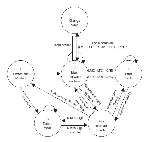
* | LME | Lock mechanism error |
LTE | Lid timeout error | |
GNR | G (Go) not received | |
EES | Excessive entry speed | |
ROE | Rack overtravel error | |
RNC | Rack not connected |