Interpolator Card Troubleshooting
Debug function - Status LatchClicking on the 'Status Latch' tab shows the errors latched for all three axes.
Any of the errors shown will cause the UCC to report a readhead error. This tab allows the error to be identified. The latest latched errors can be viewed by clicking the 'Update' button.
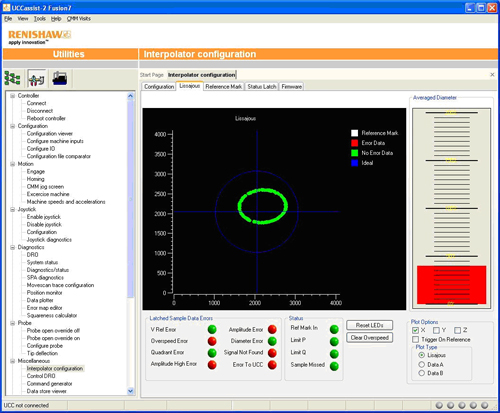
Debug function – LissajousClicking on the ‘Lissajous’ tab allows the readhead signal to be viewed graphically as well displaying the latched errors and the current Reference Mark and limit switch status.
Select the axis to view using the 'Plot Options' in the bottom right corner. The axis signals will be shown on the main graph and should form a circular Lissajous figure as the CMM moves. The blue circle indicates the ideal signal. A green data point on the Lissajous figure indicates the signal is OK. Any errors detected will turn the Lissajous data point red. When the readhead passes over a reference mark, the Lissajous data point will turn white. The phase and quadrature signals can also be plotted against time. Select the 'Data A' or 'Data B' option. The bar graph on the right indicates the signal strength compared to the ideal value (100%). Any errors in the data points are latched in the ‘Latched Sample Data Errors’ box and updated by clicking on ‘Reset LEDs’. The Interpolator PCB LED lights blue when an over speed error is detected. This error is latched within the interpolator so that it can be easily diagnosed without a site visit. The latched error is cleared by clicking on the ‘Clear Overspeed’ button. The Lissajous figure can indicate the start/stop points of the reference mark to allow optimum adjustment. Select this option by clicking on ‘Trigger On Reference’. This may require the CMM to be repeatedly run over the reference mark to build up the data points
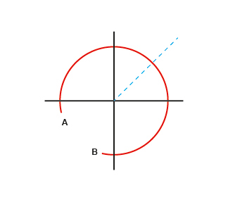
Using the reference mark trace on the lissajous, the reference mark pick up magnet can be physically adjusted so that the beginning and end points (A and B) are opposite the 45 degress (dotted line) of the lissajous as shown. Click here to return to Interpolator installation guide index page |